
2 layers148 × 81 mm
Communicator pcb
Hack-a-Day/2025-Communicator_Badge
The 2025 Hackaday Supercon RF Communicator Badge
58 parts107MIT

Wearable smartwatch PCB based on ESP32-S3 integrating IMU-based step tracking, temperature sensing, barometric sensing, Bluetooth connectivity, and display/touch interfaces
Stryd is an open-source printed circuit board by kishantm1, from the kishantm1/smartwatch-pcb repository on GitHub. It is a 2-layer board with 34 parts on 55 nets, routed with 559 tracks and 79 vias.
It is built around the ESP32-S3-WROOM-1-N8 and AP2112K-3.3. Its parts include 13 capacitors, 9 resistors, 6 ICs, 3 connectors and 2 switches. It belongs with the wearables and radio and wireless boards and the ESP32 boards of this library.


Wearable smartwatch PCB based on ESP32-S3 integrating IMU-based step tracking, temperature sensing, barometric pressure sensing, Bluetooth connectivity, and display/touch interfaces. This project focused on end-to-end wearable hardware development, including BOM creation, schematic design, PCB layout, reflow soldering, board testing, and firmware development.
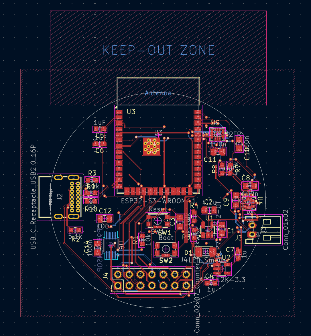
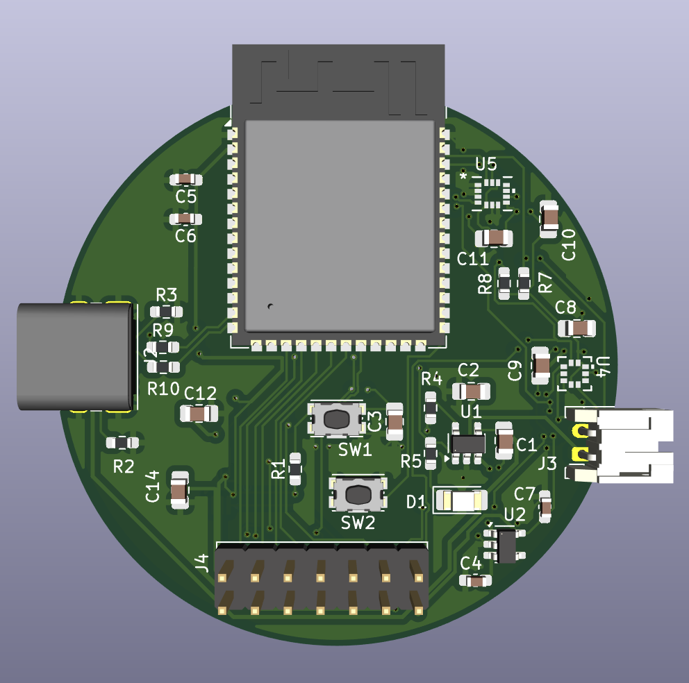
The board is centered around the ESP32-S3 microcontroller and integrates sensing, display, power, and programming/debug circuitry into a compact smartwatch PCB.
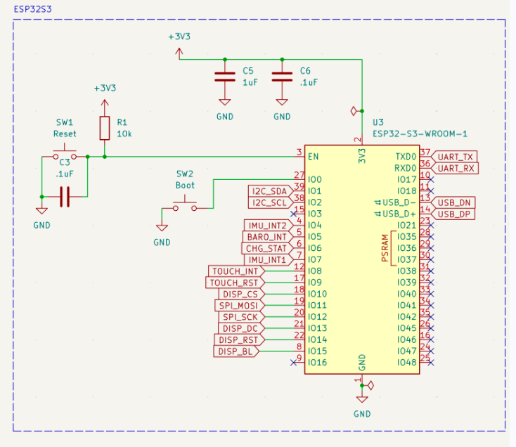
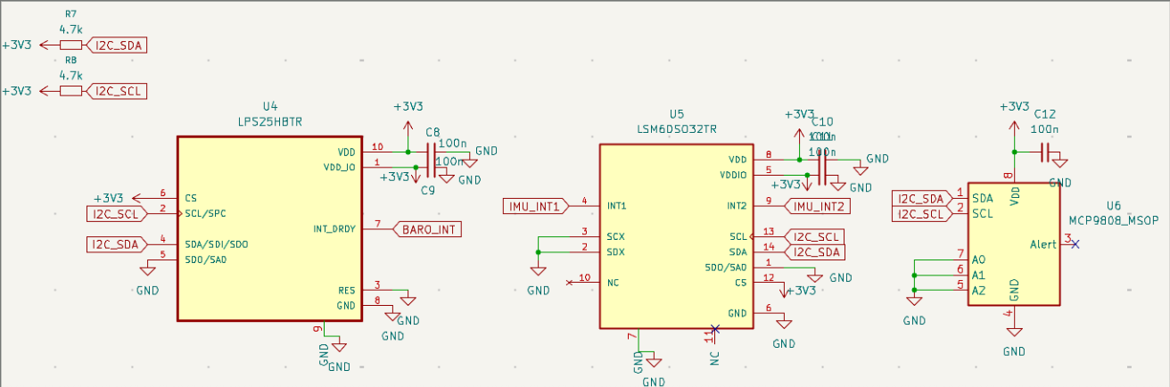
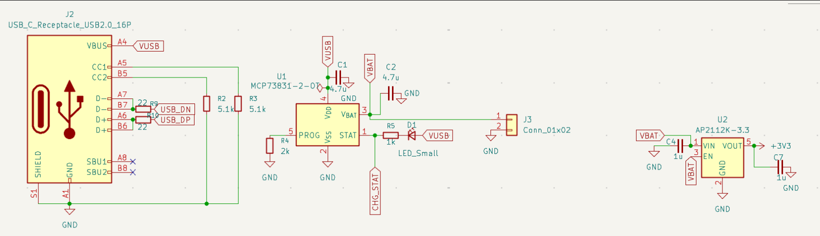
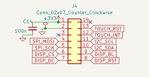
The 2-layer PCB layout was designed to fit within a compact smartwatch form factor while routing sensor, display/touch, and power connections.
 ## Assembly
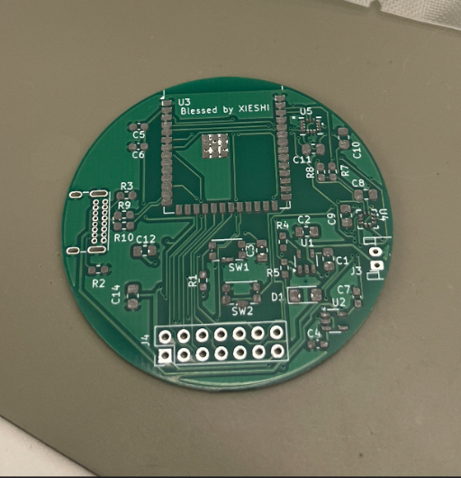
The board was assembled using solder paste, manual component placement, and reflow soldering.
Solder paste applied
Components placed
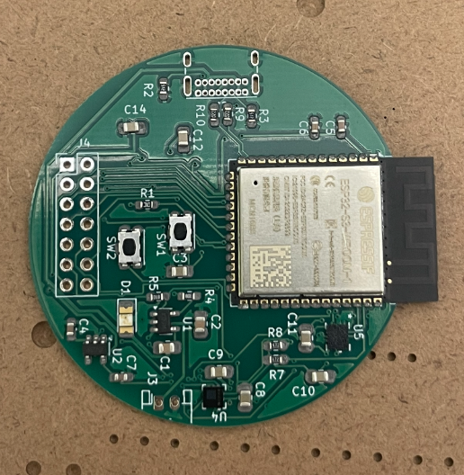
After heating in oven
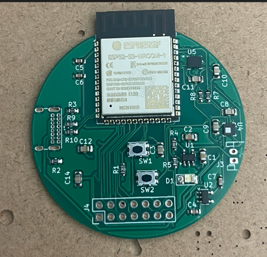
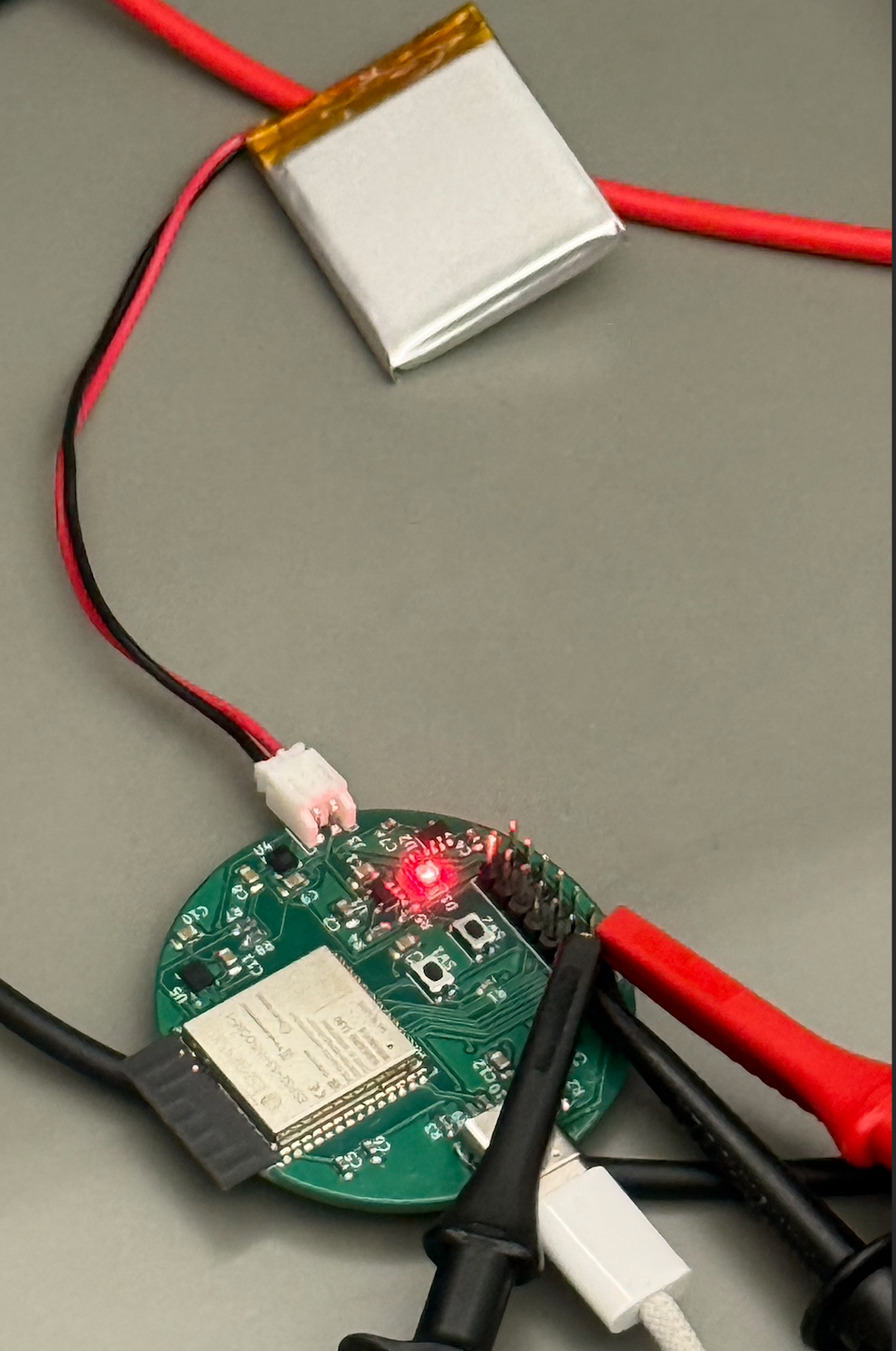
Initial testing focused on basic board functionality and power validation.
Testing included:
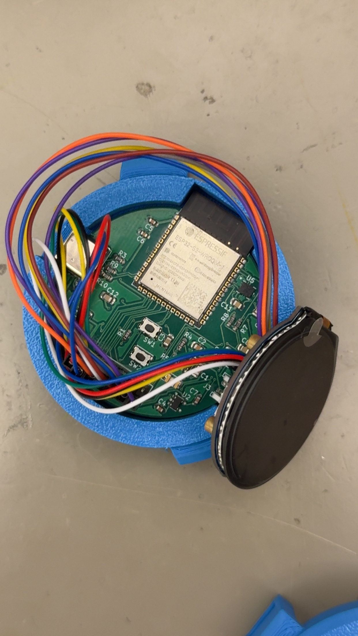
Front side
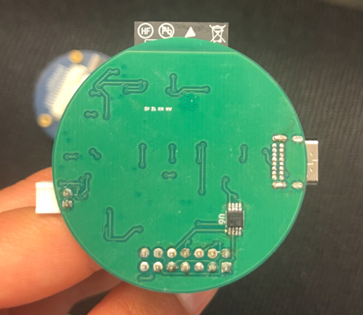
Back side
The firmware runs on the ESP32-S3 and ties together everything the watch does from reading sensors, driving the display, handling touch input, and communicating wirelessly over both Bluetooth and WiFi. Rather than pausing to wait on one task before starting the next, each subsystem (sensor sampling, display redraws, BLE updates) runs on its own independent timer. Sensors are read once a second, the screen redraws once a second, and BLE pushes updates every five seconds, but none of these ever block each other. Touch input is checked continuously in between, so the watch always feels responsive instead of freezing while it waits on a sensor or a network request.
Motion is measured with a 6-axis IMU (accelerometer + gyroscope), connected to the ESP32-S3 over I2C. Rather than calculating steps in software from raw motion data, the firmware offloads step detection to the pedometer algorithm built directly into the IMU itself. The IMU's embedded pedometer engine detects step patterns on-chip and maintains an internal step counter that the ESP32-S3 reads during operation. This reduces processing overhead on the ESP32-S3 by allowing the IMU's dedicated hardware engine to handle step detection.
Skin temperature and barometric pressure are read from two more I2C sensors. The pressure sensor's raw reading is converted into an estimated altitude using a standard atmospheric pressure formula, since pressure decreases predictably with elevation. Both values feed directly into the on-screen health and environment displays.
The watch figures out where it is and what time it is without ever needing to pair with a phone. On boot, the watch connects to WiFi and queries a geolocation API using its public IP address. This returns both approximate coordinates and a UTC time zone offset, without requiring GPS hardware. Separately, the watch syncs its clock over the network using NTP (Network Time Protocol), which provides an accurate current time from public time servers, but only in UTC. Since NTP alone doesn't know what time zone the watch is actually in, the geolocation offset is applied on top of that synced time to shift it to the correct local time. The same location lookup also feeds current local weather conditions, so a single lookup on boot supports both features and avoids relying on any hardcoded location.
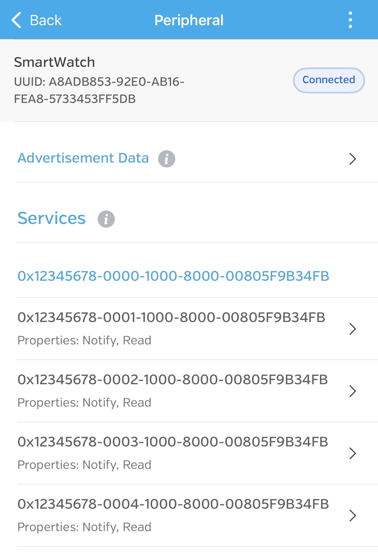
The ESP32-S3 runs a Bluetooth Low Energy (BLE) GATT server that organizes the watch's sensor data, including step count, skin temperature, pressure, and altitude, as a set of services and characteristics that any nearby device can connect to. This was confirmed using a generic BLE inspection app, LightBlue, which connected to the watch and read back the correct decoded value for each characteristic. The image shows the app discovered the watch's custom Health Service along with its four characteristics.
Navigation is handled by a capacitive touch controller, also connected over I2C. Rather than continuously polling the controller to check for input, the firmware relies on an interrupt. The touch controller itself signals the ESP32 the instant a gesture occurs. Swipe gestures move between the watch's three screens.
The firmware maintains a central watch state containing the latest sensor measurements, connectivity status, and interface state. Each screen reads from this shared state and renders the corresponding information to the display.
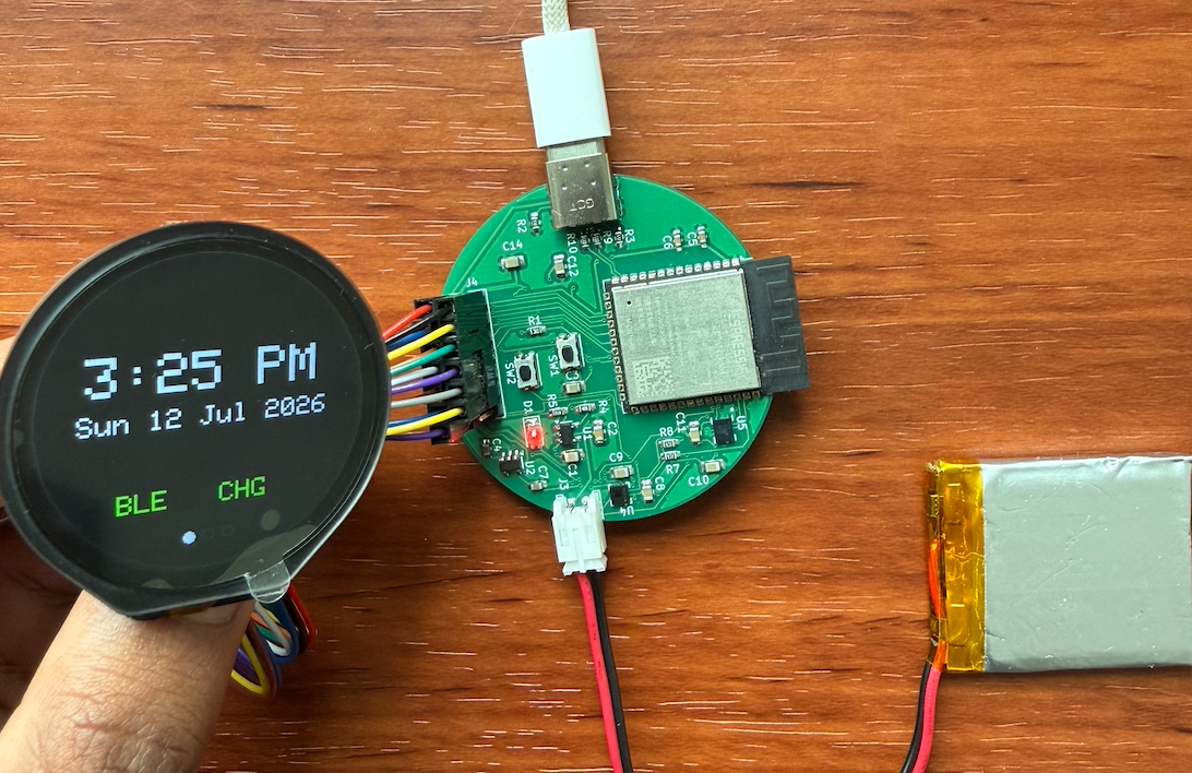
Home screen: Time, Date, Bluetooth & Battery Status
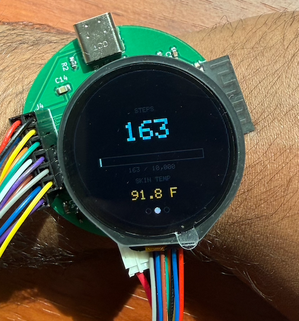
Health screen: Step Count & Skin Temperature
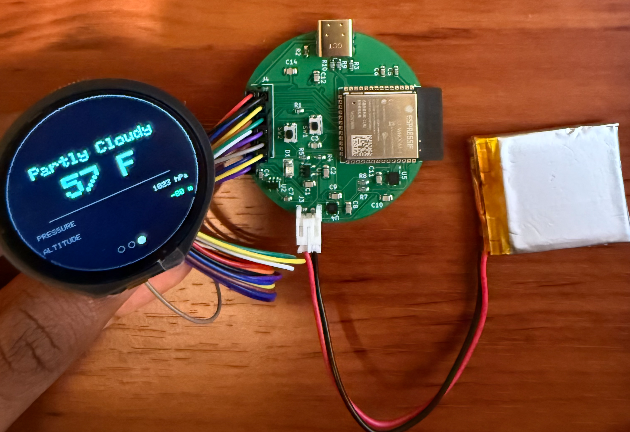
Environment screen: Weather, Barometric Pressure & Altitude
| Qty | Value | Footprint | References |
|---|---|---|---|
| 6 | 100n | Capacitor_SMD:C_0805_2012Metric_Pad1.18x1.45mm_HandSolder | C8, C9, C10, C11, C12, C14 |
| 2 | 1u | Capacitor_SMD:C_0603_1608Metric_Pad1.08x0.95mm_HandSolder | C4, C7 |
| 2 | 22 | Resistor_SMD:R_0603_1608Metric_Pad0.98x0.95mm_HandSolder | R9, R10 |
| 2 | 4.7k | Resistor_SMD:R_0603_1608Metric_Pad0.98x0.95mm_HandSolder | R7, R8 |
| 2 | 4.7u | Capacitor_SMD:C_0805_2012Metric_Pad1.18x1.45mm_HandSolder | C1, C2 |
| 2 | 5.1k | Resistor_SMD:R_0603_1608Metric_Pad0.98x0.95mm_HandSolder | R2, R3 |
| 1 | .1uF | Capacitor_SMD:C_0603_1608Metric_Pad1.08x0.95mm_HandSolder | C6 |
| 1 | .1uF | Capacitor_SMD:C_0805_2012Metric_Pad1.18x1.45mm_HandSolder | C3 |
| 1 | 10k | Resistor_SMD:R_0603_1608Metric_Pad0.98x0.95mm_HandSolder | R1 |
| 1 | 1k | Resistor_SMD:R_0603_1608Metric_Pad0.98x0.95mm_HandSolder | R5 |
| 1 | 1uF | Capacitor_SMD:C_0603_1608Metric_Pad1.08x0.95mm_HandSolder | C5 |
| 1 | 2k | Resistor_SMD:R_0603_1608Metric_Pad0.98x0.95mm_HandSolder | R4 |
| 1 | AP2112K-3.3 | Package_TO_SOT_SMD:SOT-23-5 | U2 |
| 1 | Boot | Button_Switch_SMD:SW_Push_1P1T-SH_NO_CK_KMR2xxG | SW2 |
| 1 | Conn_01x02 | Connector_JST:JST_PH_S2B-PH-K_1x02_P2.00mm_Horizontal | J3 |
| 1 | Conn_02x07_Counter_Clockwise | Connector_PinHeader_2.54mm:PinHeader_2x07_P2.54mm_Vertical | J4 |
| 1 | ESP32-S3-WROOM-1 | RF_Module:ESP32-S3-WROOM-1 | U3 |
| 1 | LED_Small | LED_SMD:LED_1206_3216Metric_Pad1.42x1.75mm_HandSolder | D1 |
| 1 | LPS25HBTR | Library:HLGA10_2P5X2P5_STM U4 | U4 |
| 1 | LSM6DSO32TR | Library:LGA-14L_2P5X3X0P83_STM | U5 |
| 1 | MCP73831-2-OT | Package_TO_SOT_SMD:SOT-23-5 | U1 |
| 1 | MCP9808_MSOP | Package_SO:MSOP-8_3x3mm_P0.65mm | U6 |
| 1 | Reset | Button_Switch_SMD:SW_Push_1P1T-SH_NO_CK_KMR2xxG | SW1 |
| 1 | USB_C_Receptacle_USB2.0_16P | Connector_USB:USB_C_Receptacle_GCT_USB4085 | J2 |
Hack-a-Day/2025-Communicator_Badge
The 2025 Hackaday Supercon RF Communicator Badge

jfwoods/insta360link-controller
A lightweight daemon, CLI tool, and (optional) firmware + hardware for controlling an Insta360 Link webcam without the first-party software.

rowr111/blinky-badge-light
lighting badge with unique patterns and sound reactivity

DimitriOnLSD/imu-rc
Gesture-based RC car controller using ESP32-S3, BLE, LSM6DSO IMU, OLED display, and LiPo battery with USB-C charging.


milovanpms/talk-e
📻 — A simple LoRa-based talkie-walkie built on ESP32, operating on the 433 MHz frequency band for long-range, low-power wireless communication.

rapha-tech/ESP32-hema-console
New PCB for the small console from hema to use an ESP32

34 parts, built around the ESP32-S3-WROOM-1-N8 and AP2112K-3.3. The full list of its parts is on this page, with links to each part's symbol and footprint where PCBKit's library has them.
From the kishantm1/smartwatch-pcb repository on GitHub, at the commit this page was made from: the board is kicad_project/stryd.kicad_pcb and its schematic kicad_project/display.kicad_sch. PCBKit opens the board in the browser, with nothing to install.
Its repository states no licence, so its author keeps all rights: ask kishantm1 before reusing the design.