
2 layers65 × 30 mm
Rgb to hdmi
hoglet67/RGBtoHDMI
Bare-metal Raspberry Pi project that provides pixel-perfect sampling of Retro Computer RGB/YUV video and conversion to HDMI
33 parts1kGPL-3.0

 KhaledGhanem0/PCB-Shield-Security-System1
KiCad PCB shield design for an Arduino Mega-based multi-zone security system. Two-layer, through-hole, hand-solderable board replacing the breadboard prototype.
Security System Arduino Shield is an open-source printed circuit board by KhaledGhanem0, from the KhaledGhanem0/PCB-Shield-Security-System repository on GitHub, published under the MIT licence. It is a 2-layer board of 100.6 × 78.2 mm with 33 parts on 97 nets, routed with 283 tracks and 12 vias.
Its parts include 21 connectors, 3 diodes and 1 resistor. It belongs with the microcontroller boards boards and the AVR (ATmega, ATtiny) boards of this library.



A custom two-layer Arduino Mega shield PCB designed to replace the breadboard prototype of the Multi-Zone Smart Security System. The board consolidates all control and sensing connections into a single, permanent, and reliable hardware platform.
🔗 Firmware Repository: Multi-Zone Smart Security System
This project is a direct continuation of the Multi-Zone Smart Security System. The breadboard prototype, while functional, was not a reliable or permanent form factor. This shield was designed in KiCad to produce a clean, manufacturable PCB that sits directly on top of the Arduino Mega 2560 and exposes all the necessary connectors for the system's peripherals.
The design follows standard Arduino shield dimensions, ensuring mechanical compatibility with the Mega footprint. All components are through-hole (THT), making the board straightforward to solder by hand. The schematic was drawn as a single sheet with clear net labeling, and the PCB layout was routed with dedicated power and signal trace widths, a ground copper pour on the back copper layer, and a defined keep-out zone to avoid interference with the Arduino's onboard components.
The schematic captures the complete connectivity of all shield components in a single sheet. Each peripheral is connected to the appropriate Arduino Mega pins, with net labels used throughout to keep the diagram readable and avoid long crossing wires.
Key connections documented in the schematic:
The PCB is sized to match Arduino Mega shield dimensions, with connectors positioned to align with the Mega's header rows. Components are placed on the front side only (all THT). A keep-out zone is defined over the Arduino's onboard USB and power jack area to prevent clearance violations.
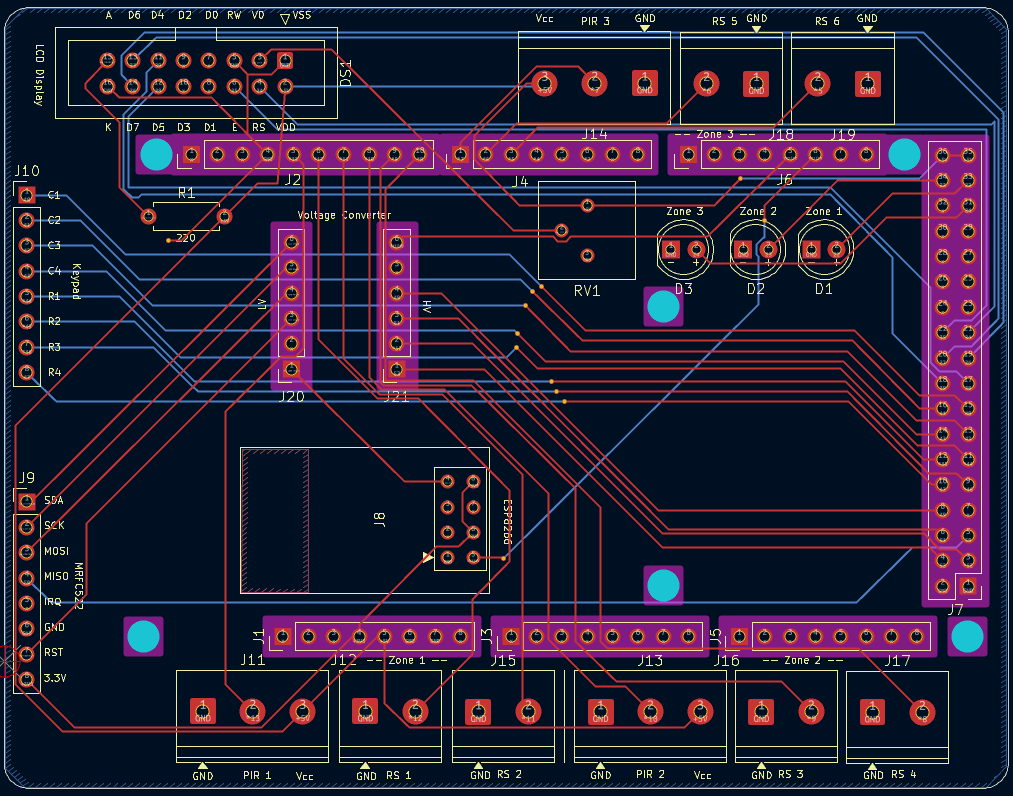
Routing highlights:
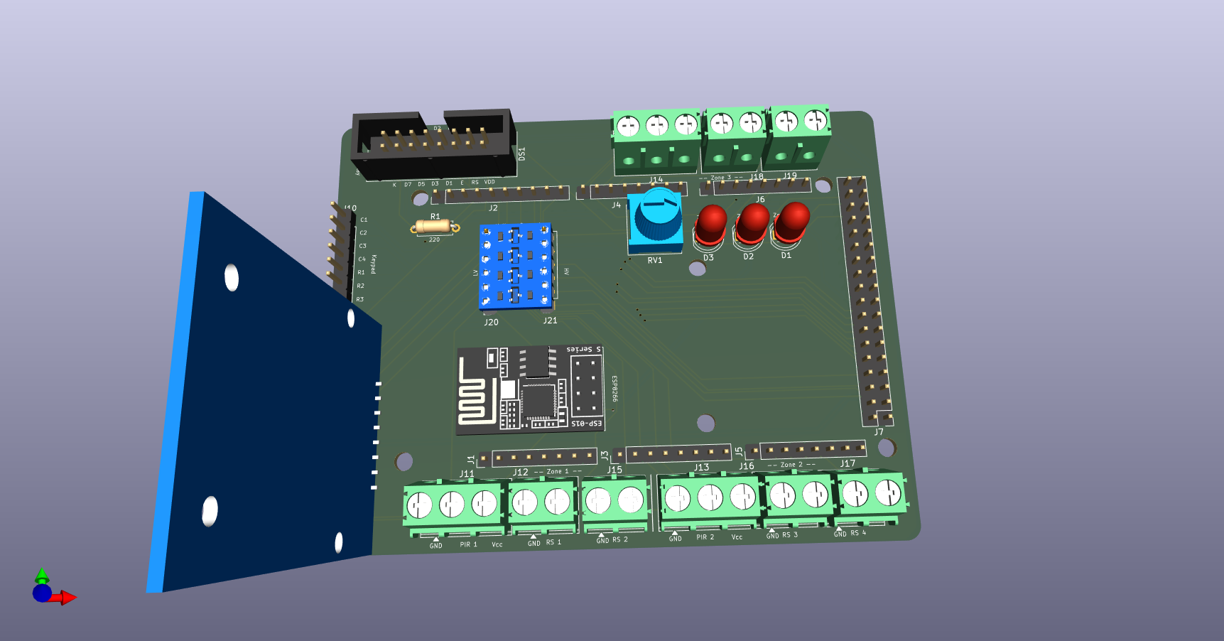
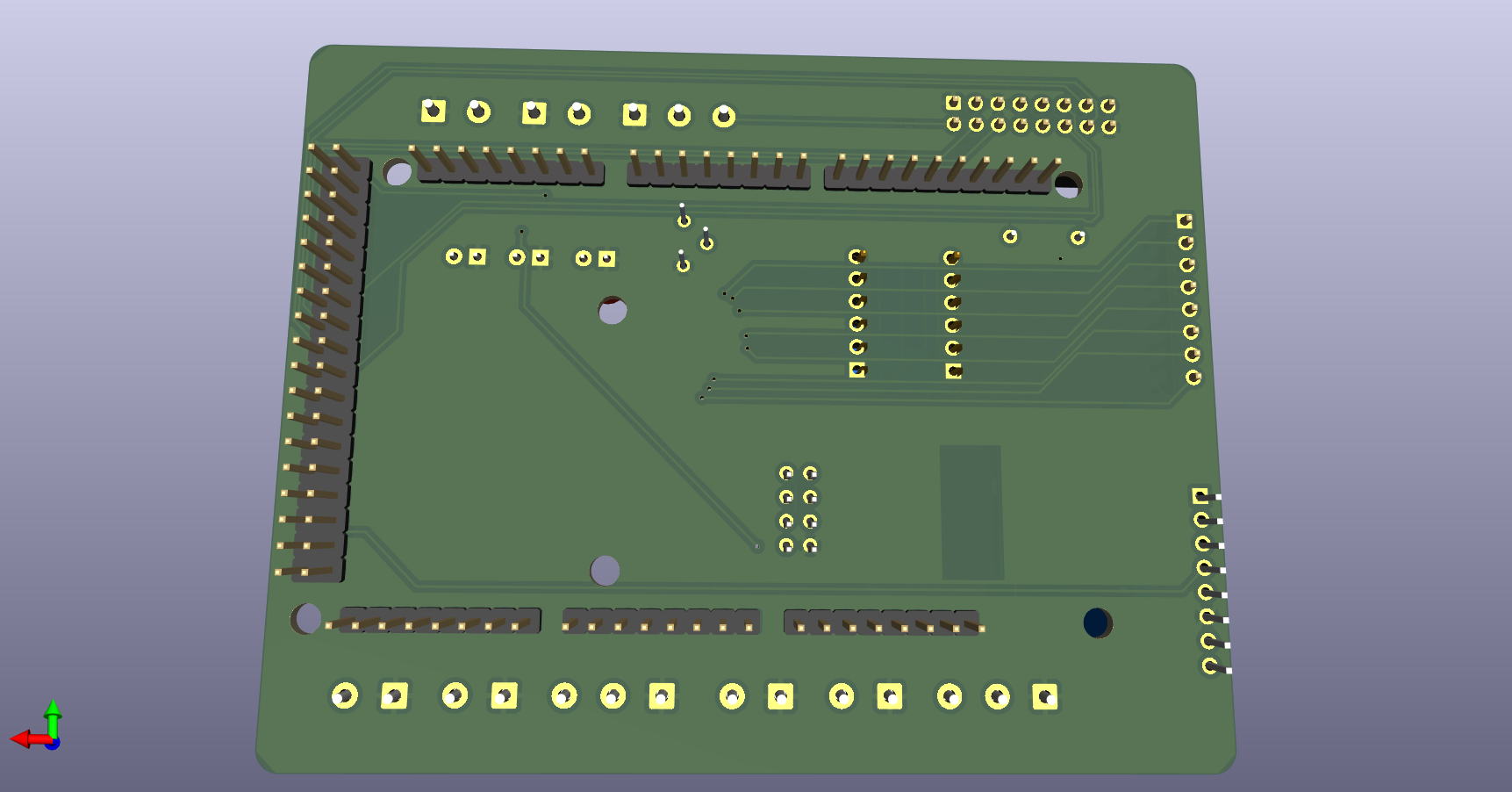
The images below show the KiCad 3D render of the board before fabrication. All component footprints are placed on the front side of the board.
Front
Back
| Layer | Type | Thickness | Material |
|---|---|---|---|
| F.Silkscreen | Top Silk Screen | — | — |
| F.Paste | Top Solder Paste | — | — |
| F.Mask | Top Solder Mask | 0.01 mm | — |
| F.Cu | Copper | 0.035 mm | — |
| Dielectric 1 | Core | 1.51 mm | FR4 |
| B.Cu | Copper | 0.035 mm | — |
| B.Mask | Bottom Solder Mask | 0.01 mm | — |
| B.Paste | Bottom Solder Paste | — | — |
| B.Silkscreen | Bottom Silk Screen | — | — |
Total board thickness: 1.6 mm | Solder mask color: Green
| Property | Value |
|---|---|
| Width | 100.584 mm |
| Height | 78.232 mm |
| Area | 7,863 mm² |
| Parameter | Value |
|---|---|
| Signal trace width | 0.25 mm |
| Power trace width | 0.50 mm |
| Minimum clearance | 0.2 mm |
| Copper to edge clearance | 0.075 mm |
| Minimum via diameter | 0.4 mm |
| Minimum drill (through hole) | 0.3 mm |
| Hole to hole clearance | 0.25 mm |
| Item | Count |
|---|---|
| THT components | 27 |
| Through-hole pads | 170 |
| NPTH (mounting holes) | 6 |
| Through vias | 12 |
| Total components | 33 |
The table below lists the components used on the shield.
| Reference | Value / Description | Footprint | Qty |
|---|---|---|---|
| DS1 | WC1602A (LCD Screen) | IDC Header 2×8, 2.54 mm | 1 |
| J1 | Power Header | Pin Header 1×8, 2.54 mm | 1 |
| J2 | PWM Header | Pin Header 1×10, 2.54 mm | 1 |
| J3, J5 | Analog Headers | Pin Header 1×8, 2.54 mm | 2 |
| J4 | PWM Header | Pin Header 1×8, 2.54 mm | 1 |
| J6 | Communication Header | Pin Header 1×8, 2.54 mm | 1 |
| J7 | Digital Header | Pin Header 2×18, 2.54 mm | 1 |
| J8 | ESP-01 (ESP8266 Wi-Fi Module) | ESP-01 Module Footprint | 1 |
| J9, J10 | Connectors 1×8 | Pin Header 1×8, 2.54 mm | 2 |
| J11, J13, J14 | Screw Terminal 3-pin (PIR Sensors) | Phoenix PT 1×3, 5.0 mm | 3 |
| J12, J15, J16, J17, J18, J19 | Screw Terminal 2-pin (Reed Switches) | Phoenix PT 1×2, 5.0 mm | 6 |
| J20, J21 | Socket Connectors 1×6 | Pin Socket 1×6, 2.54 mm | 2 |
| D1, D2, D3 | LED 5 mm (Zone Alarms) | LED THT, D5.0 mm | 3 |
| R1 | Resistor 220 Ω | Axial DIN0207, 7.62 mm pitch | 1 |
| RV1 | Potentiometer (LCD Contrast) | Bourns 3386P Vertical | 1 |
├── kicad/
│   ├── Security System Arduino Shield.kicad_pro   # KiCad project file
│   ├── Security System Arduino Shield.kicad_sch   # Schematic
│   ├── Security System Arduino Shield.kicad_pcb   # PCB layout
│   └── fp-lib-table                               # Footprint library references
├── images/
│   ├── schematic.pdf                              # Schematic PDF
│   ├── pcb_layout.png                             # PCB layout screenshot
│   ├── 3d_front.png                               # 3D render, front side
│   └── 3d_back.png                                # 3D render, back side
├── LICENSE
└── README.mdThis project is licensed under the MIT License.
| Qty | Value | Footprint | References |
|---|---|---|---|
| 6 | MountingHole_3.2mm | Arduino_MountingHole:MountingHole_3.2mm | MH1, MH2, MH3, MH4, MH5, MH6 |
| 6 | Screw_Terminal_01x02 | TerminalBlock_Phoenix:TerminalBlock_Phoenix_PT-1,5-2-5.0-H_1x02_P5.00mm_Horizontal | J12, J15, J16, J17, J18, J19 |
| 3 | LED | LED_THT:LED_D5.0mm | D1, D2, D3 |
| 3 | Screw_Terminal_01x03 | TerminalBlock_Phoenix:TerminalBlock_Phoenix_PT-1,5-3-5.0-H_1x03_P5.00mm_Horizontal | J11, J13, J14 |
| 2 | Analog | Connector_PinHeader_2.54mm:PinHeader_1x08_P2.54mm_Vertical | J3, J5 |
| 2 | Conn_01x06_Socket | Connector_PinSocket_2.54mm:PinSocket_1x06_P2.54mm_Vertical | J20, J21 |
| 2 | Conn_01x08 | Connector_PinHeader_2.54mm:PinHeader_1x08_P2.54mm_Vertical | J9, J10 |
| 1 | 220 | Resistor_THT:R_Axial_DIN0207_L6.3mm_D2.5mm_P7.62mm_Horizontal | R1 |
| 1 | Communication | Connector_PinHeader_2.54mm:PinHeader_1x08_P2.54mm_Vertical | J6 |
| 1 | Conn_02x04_Odd_Even | RF_Module:ESP-01 | J8 |
| 1 | Digital | Connector_PinHeader_2.54mm:PinHeader_2x18_P2.54mm_Vertical | J7 |
| 1 | PWM | Connector_PinHeader_2.54mm:PinHeader_1x08_P2.54mm_Vertical | J4 |
| 1 | PWM | Connector_PinHeader_2.54mm:PinHeader_1x10_P2.54mm_Vertical | J2 |
| 1 | Power | Connector_PinHeader_2.54mm:PinHeader_1x08_P2.54mm_Vertical | J1 |
| 1 | R_Potentiometer | Potentiometer_THT:Potentiometer_Bourns_3386P_Vertical | RV1 |
| 1 | WC1602A | Connector_IDC:IDC-Header_2x08_P2.54mm_Vertical | DS1 |
It measures 100.6 × 78.2 mm and has 2 copper layers, 1.6 mm thick.
33 parts. The full list of its parts is on this page, with links to each part's symbol and footprint where PCBKit's library has them.
From the KhaledGhanem0/PCB-Shield-Security-System repository on GitHub, at the commit this page was made from: the board is kicad/Security System Arduino Shield.kicad_pcb and its schematic kicad/Security System Arduino Shield.kicad_sch. PCBKit opens the board in the browser, with nothing to install.
Its repository publishes it under the MIT licence: you may reuse it on that licence's terms (keep the author's notice, and for a copyleft licence share your changes alike).
hoglet67/RGBtoHDMI
Bare-metal Raspberry Pi project that provides pixel-perfect sampling of Retro Computer RGB/YUV video and conversion to HDMI

mntmn/amiga2000-gfxcard
MNT VA2000, an Open Source Amiga 2/3/4000 Graphics Card (Zorro II/III), written in Verilog

hackclub/OnBoard
💡 Join 1,000 teenagers and make your first PCB with a $100 grant!

Arrow-air/project-quiver
Project Quiver documentation, designs, and project artifacts.

ozel/DIY_particle_detector
A mobile low-cost spectrometer for measuring radioactivity and the energy of ionising radiation like alpha particles and electrons

BlueAndi/Pixelix
Full RGB LED matrix, based on an ESP32 and WS2812B LEDs or emulated LEDs on TFT.

jrsteensen/OpenHornet
OpenHornet 1:1 F/A-18C Simulator Repository
