

2 layers22.2 × 46.4 mm
C64-Switchless Quad Kernal Switcher
bwack/C64-Switchless-Multi-Kernal-27C256-adapter
Kernal switcher for the C64/C64C/C128
14 parts112
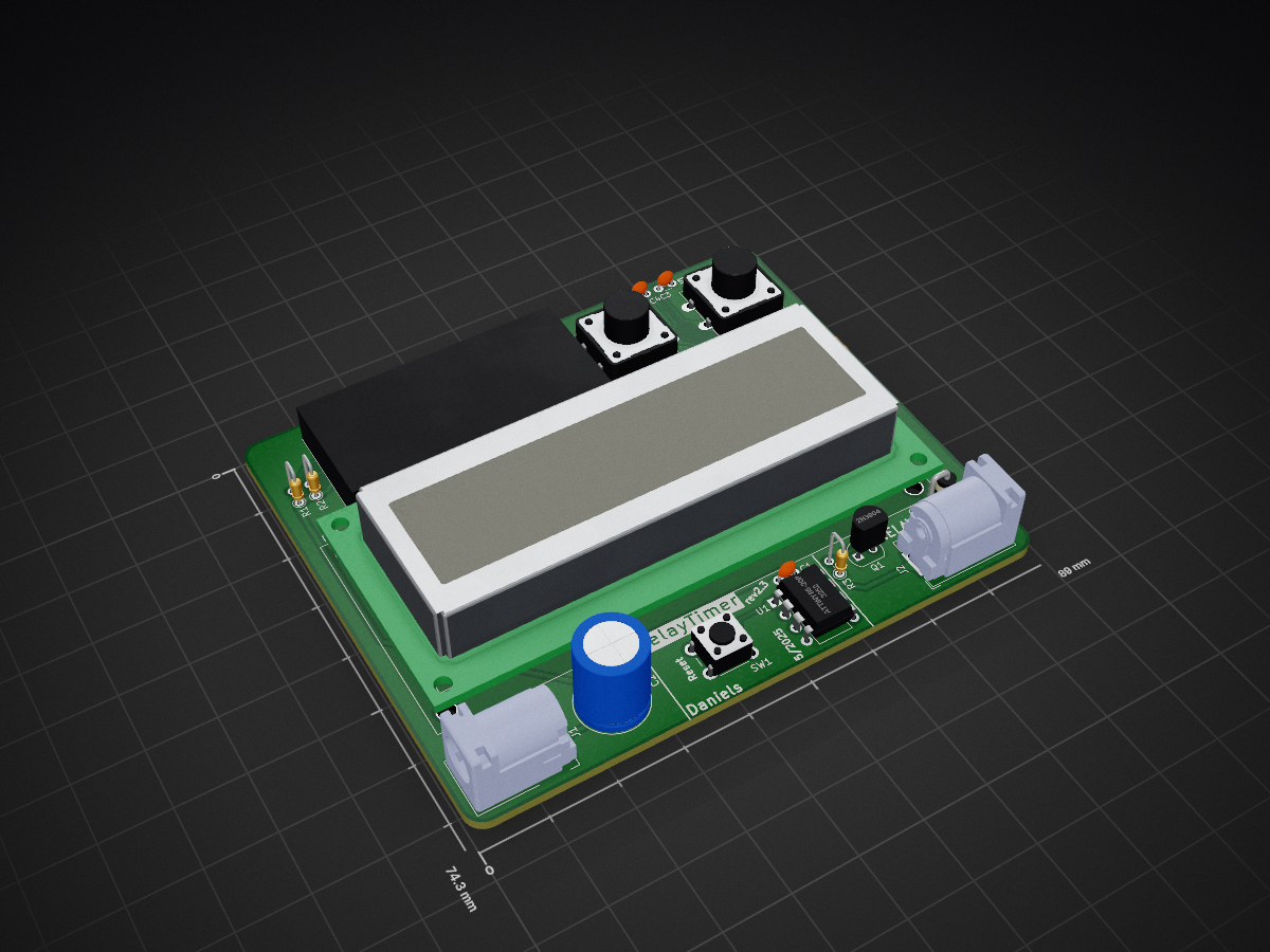
 KDDaniels/RelayTimer
Simple timer with a two button interface and LCD screen to show the time remaining. Intended to control a relay but could be used for anything else really.
RelayTimer is an open-source printed circuit board by KDDaniels, from the KDDaniels/RelayTimer repository on GitHub, published under the GPL-3.0 licence. It is a 2-layer board of 89 × 74.3 mm with 19 parts on 26 nets, routed with 99 tracks and 0 vias.
It is built around the ATTINY85-20PU. Its parts include 5 resistors, 4 capacitors, 2 connectors, 1 IC and 1 diode. It belongs with the AVR (ATmega, ATtiny) boards of this library.

Simple timer with a two button interface and LCD screen to show the time remaining. Intended to control a relay but could be used for anything else really.
I couldn't find it on the PlatformIO library explorer, but this project requires the LiquidCrystal_attiny library.
Intended for an ATtiny85, this could definitely be ported to other microcontrollers if needed. Will need slight adjustment due to the direct port register manipulation though.
             ATtiny85
             __   __
 NC <- PB5 =|1 *-* 8|= VCC <- +5v
 FB <- PB3 =|2     7|= PB2 -> SCL
 TB <- PB4 =|3     6|= PB1 -> Relay
GND <- GND =|4_____5|= PB0 -> SDA| Qty | Value | Footprint | References |
|---|---|---|---|
| 3 | 0.1uF | Capacitor_THT:C_Disc_D3.0mm_W1.6mm_P2.50mm | C1, C3, C4 |
| 2 | 1k | Resistor_THT:R_Axial_DIN0204_L3.6mm_D1.6mm_P7.62mm_Horizontal | R6, R7 |
| 2 | 4k7 | Resistor_THT:R_Axial_DIN0204_L3.6mm_D1.6mm_P2.54mm_Vertical | R1, R2 |
| 2 | SW_Push | Button_Switch_THT:SW_PUSH-12mm | FUNCTION1, START/STOP1 |
| 1 | 1k | Resistor_THT:R_Axial_DIN0204_L3.6mm_D1.6mm_P2.54mm_Vertical | R3 |
| 1 | 2N3904 | Package_TO_SOT_THT:TO-92 | Q1 |
| 1 | 300uF | Capacitor_THT:C_Radial_D10.0mm_H12.5mm_P5.00mm | C2 |
| 1 | ATtiny85-20P | Package_DIP:DIP-8_W7.62mm | U1 |
| 1 | D | Diode_THT:D_DO-41_SOD81_P2.54mm_Vertical_KathodeUp | D1 |
| 1 | Jack-DC | Connector_BarrelJack:BarrelJack_GCT_DCJ200-10-A_Horizontal | J1 |
| 1 | Relay_Con | Connector_BarrelJack:BarrelJack_GCT_DCJ200-10-A_Horizontal | J2 |
| 1 | SW_Push | Button_Switch_THT:SW_PUSH_6mm | SW1 |
| 1 | WC1602A | Display:WC1602A | DS1 |
| 1 | ~ | custom_stuff:PCF8574T | PCF8574T_Board1 |
It measures 89 × 74.3 mm and has 2 copper layers, 1.6 mm thick.
19 parts, built around the ATTINY85-20PU. The full list of its parts is on this page, with links to each part's symbol and footprint where PCBKit's library has them.
From the KDDaniels/RelayTimer repository on GitHub, at the commit this page was made from: the board is RelayTimer/RelayTimer.kicad_pcb and its schematic RelayTimer/RelayTimer.kicad_sch. PCBKit opens the board in the browser, with nothing to install.
Its repository publishes it under the GPL-3.0 licence: you may reuse it on that licence's terms (keep the author's notice, and for a copyleft licence share your changes alike).
bwack/C64-Switchless-Multi-Kernal-27C256-adapter
Kernal switcher for the C64/C64C/C128

plusvic/simplebus2-intercom
General description of the Simplebus2 protocol used by some Comelit's intercoms. Hardware for retransmitting Simplebus2 messages over UART.

osmocom/osmocom-analog
Software Implementation of analog cellular telephony systems like NMT, TACS, IMTS, A/B/C-Netz; mirror of https://gitea.osmocom.org/cellular-infrastructure/osmocom-analog

strickyak/jerboa-attiny85-mod-synth
Modular Synthesizer using an ATtiny85 chip for each module.


Hack-a-Day/Remoticon_KiCad_Blender
support files for the 2020 Remoticon KiCad to Blender > PCB renders workshop
