
2 layers90 × 52 mm

 kazushinjo/Shonan_lite-PI41
DATV Tranceiver Shonan_Lite for Raspberry Pi 4 with Langstone-V2Modify+ Pluto v0.32-dirty
Audio ptt control is an open-source printed circuit board by kazushinjo, from the kazushinjo/Shonan_lite-PI4 repository on GitHub. It is a 2-layer board of 57.3 × 49 mm with 21 parts on 10 nets, routed with 90 tracks and 0 vias.
It is built around the TLP222A-2(F). Its parts include 6 capacitors, 4 connectors, 3 resistors, 2 inductors and 1 IC. It belongs with the audio and music boards of this library.
Raspberry Pi 4 + ADALM-Pluto+によるDVB-S2 DATV送受信タッチGUIシステム。
本体はpi4/配下(Python/PyQt5。DFRobot DFR0550はlinuxfb、公式DSIタッチ画面はeglfsで描画)。同系統の別プラットフォーム
移植版(Android/iOS)は別リポジトリ(Shonan_Lite-android/Shonan_Lite-iPad等)
で管理している。
A touch-GUI DVB-S2 DATV transceiver system using a Raspberry Pi 4 and an ADALM-Pluto+.
The application lives under pi4/ (Python/PyQt5; drawn with linuxfb on the DFRobot DFR0550 and with eglfs on the
official DSI touch display). Ports to other platforms (Android/iOS) are maintained in separate repositories
(Shonan_Lite-android, Shonan_Lite-iPad, etc.).
[!IMPORTANT] Plutoのユーザー名(
root)・パスワード(analog)はデフォルト値のまま変更しないでください。 本アプリとLangstone V2Modifyは、SSHでPlutoにログインしてリブートや設定ファイルの書き込みを行っています (アプリ再起動・機器試験・送受信開始時・Langstone終了時)。変更するとPlutoをリブートできなくなります。Keep the Pluto's username (
root) and password (analog) at their default values. This app and Langstone V2Modify log in to the Pluto via SSH to reboot it and write its settings file (at app restart, equipment test, TX/RX start and Langstone exit). If they are changed, the Pluto cannot be rebooted.
pluto_dvb)で送信する(Plutoの設定はSSHで/www/settings.txtへ
書き込み、送信先ポートは8282固定)。FECは変調方式ごとに動作する組み合わせだけを選べる
(QPSK: 1/2・3/5・8/9、8PSK: 3/5・8/9)。H.264はPi 4内蔵のハードウェアエンコーダ(h264_v4l2m2m)で符号化し、
送信映像はフルHD(1920x1080)固定。音声はカメラ内蔵マイクをAAC(モノラル16kbps)で映像と一緒に送信する(マイクが無ければ無音)。送信画面には出力減衰(dB)、
Plutoへ送ったUDPパケット数、符号化したフレーム数を表示する。~/Pictures/Shonan_Lite/)を撮り、そのまま送信画像に使える。
コールサイン・備考を文字サイズ・文字色を選んで映像へ焼き込める(日時も表示)。linuxfb)と公式DSIタッチ画面(eglfs)に対応。pluto_dvb) (the Pluto settings are
written to /www/settings.txt via SSH; the destination port is fixed at 8282). Only FEC rates that work with each
modulation can be selected (QPSK: 1/2, 3/5, 8/9; 8PSK: 3/5, 8/9). H.264 is encoded with the Pi 4's hardware encoder
(h264_v4l2m2m), and the transmitted video is fixed at Full HD (1920x1080). Audio from the camera's built-in microphone is sent with the video as AAC (mono, 16 kbps); silence if no microphone is found. The TX screen shows
the attenuation (dB), the number of UDP packets sent to the Pluto and the number of encoded frames.~/Pictures/Shonan_Lite/) that can be used
directly as the transmit image. A callsign and a note can be burned into the video with a selectable text size and
color (the date and time are shown as well).linuxfb) and the official DSI
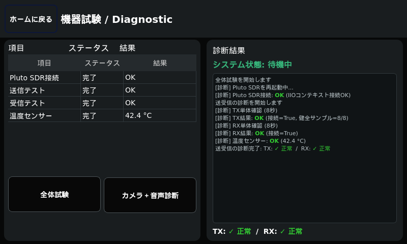
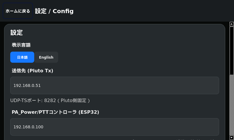
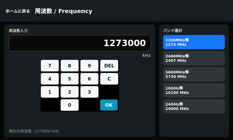
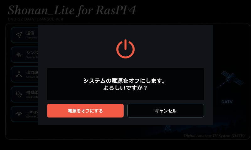
touch display (eglfs).実機(DFR0550、800x480)の画面(2026-09-25撮影)。映像はすべてテストパターンで撮影している。 送信画面は送信中、RSSI測定はオンデバイス復調ONで「1回」実行した結果(自局のテストパターン信号)。
Screens on the device (DFR0550, 800x480, taken on 2026-09-25). All video was taken with the test pattern. The TX screen is shown while transmitting, and RSSI measurement shows the result of a "Once" run with on-device demodulation ON (the station's own test-pattern signal).
| Home画面 / Home | 送信画面 / TX | 受信画面 / RX | RSSI測定 / RSSI |
|---|---|---|---|
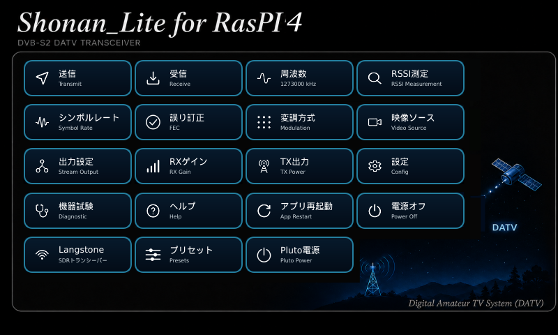 | 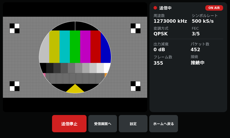 | 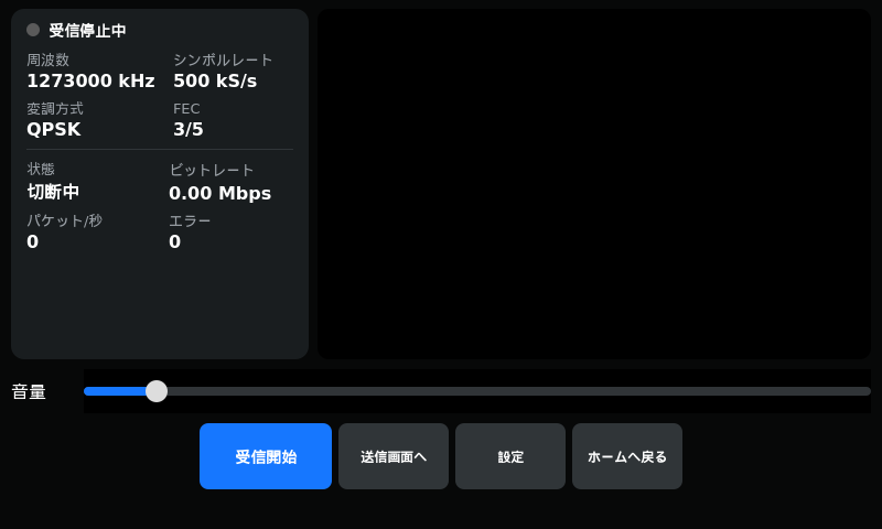 | 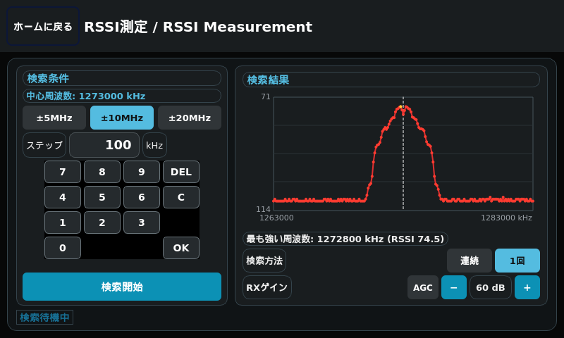 |
| 映像ソース / Video Source | 変調方式 / Modulation | 出力設定 / Stream Output | プリセット / Presets |
|---|---|---|---|
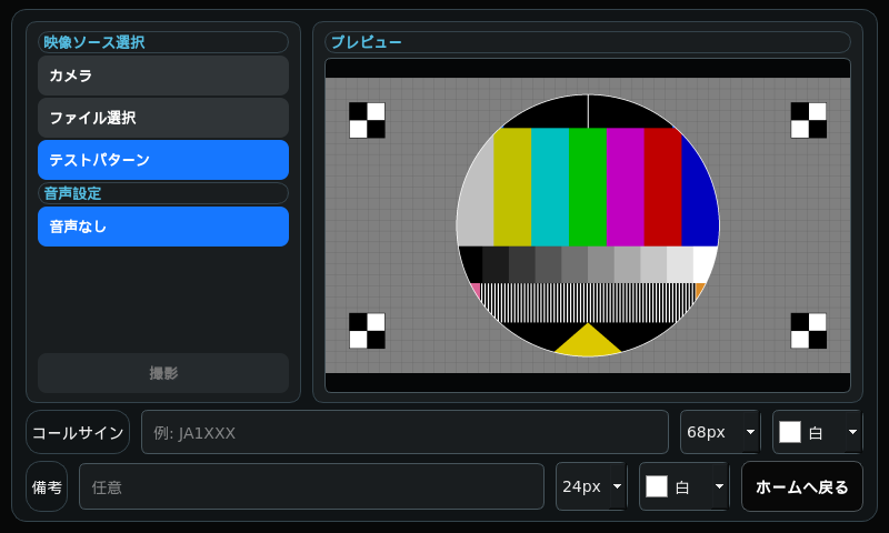 | 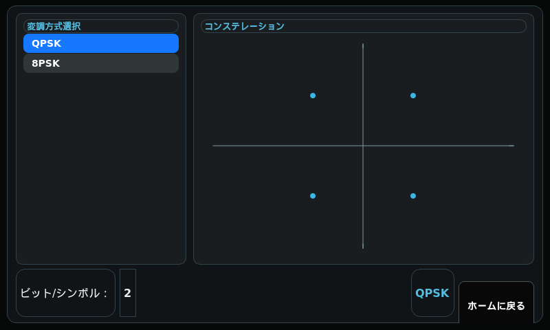 | 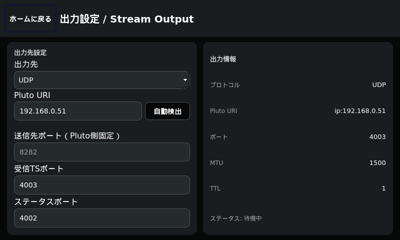 | 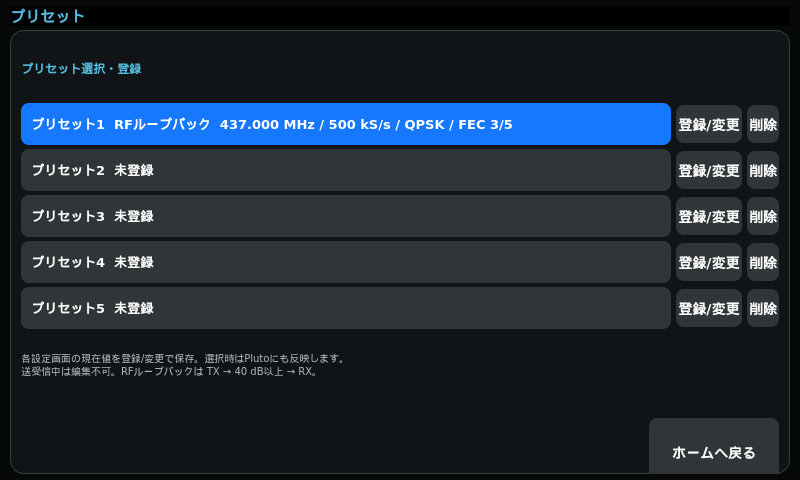 |
| 機器試験 / Diagnostic | 設定 / Config | 周波数 / Frequency | 電源オフ / Power Off |
|---|---|---|---|
 |  |  |  |
各画面の操作方法は、アプリ内の「ヘルプ」または操作説明書
pi4/docs/shonan_pi4_operation_manual.docxを参照。
For how to operate each screen, see the in-app "Help" or the operation manual
pi4/docs/shonan_pi4_operation_manual.docx.
Pi4本体に、あらかじめRaspberry Pi OSをインストールしておく。
ssh <ユーザー名>@<ホスト名>.localで接続できることを確認する。Install Raspberry Pi OS on the Pi 4 beforehand.
ssh <username>@<hostname>.local.SSH接続したPi4上で / On the Pi 4 connected via SSH:
git clone https://github.com/kazushinjo/Shonan_lite-PI4.git
cd Shonan_lite-PI4
./pi4/scripts/install.sh          # HTTPSでclone(既定) / clone via HTTPS (default)
# ./pi4/scripts/install_ssh.sh    # GitHubにSSH鍵を登録済みならこちらでも可 / or this if your SSH key is registered on GitHub
日本語入力ビルド・受信(RX)用GNU Radio/gr-dvbs2rxビルド・Langstone V2Modifyビルドは それぞれ省略して時間短縮できる(省略した機能は使えなくなる):
The Japanese input build, the GNU Radio/gr-dvbs2rx build for RX and the Langstone V2Modify build can each be skipped to save time (the skipped features will not be available):
SKIP_JA_KEYBOARD=1 SKIP_GNURADIO_BUILD=1 SKIP_LANGSTONE_BUILD=1 ./pi4/scripts/install.sh★OSを新規インストールした直後の初回実行では、DFR0550をfirmwareのレガシーDSI表示で
動かすため、install.shが最初に/boot/firmware/config.txtのdtoverlay=vc4-kms-v3d・
display_auto_detect=1・disable_fw_kms_setup=1をコメントアウトし、dtparam=i2c_arm=onを
追記して終了する。案内に従ってPi4を再起動(sudo reboot)し、同じコマンドを再実行すると
ビルドへ進む(KMS有効のままビルドすると画面・タッチが使えないうえ、実機が再起動して
パッケージが破損することを確認している)。
★On the first run right after a fresh OS install, to drive the DFR0550 with the firmware's legacy DSI display,
install.sh first comments out dtoverlay=vc4-kms-v3d, display_auto_detect=1 and disable_fw_kms_setup=1 in
/boot/firmware/config.txt, adds dtparam=i2c_arm=on, and exits. Reboot the Pi 4 as instructed (sudo reboot) and
run the same command again to proceed to the build (building with KMS enabled leaves the display and touch unusable,
and we confirmed that the device reboots and packages get corrupted).
完了後、shonan-gui.serviceがsystemdに登録されGUIが自動起動する。あわせて
/boot/firmware/config.txtへavoid_warnings=1(電源電圧警告アイコンの表示抑制)
を未設定なら自動で追記する(反映には再起動が必要)。
When finished, shonan-gui.service is registered with systemd and the GUI starts automatically. It also adds
avoid_warnings=1 (suppresses the under-voltage warning icon) to /boot/firmware/config.txt if not already set
(a reboot is required for it to take effect).
一般ユーザーが実行してinstall.shが正常完了するには、以下が必要。
gitが事前にインストール済みであることpatchコマンドが使えることFor install.sh to complete successfully when run as a normal user, the following are required.
git installed beforehandpatch command available詳細な各手順の解説・トラブルシュートは
pi4/docs/install_script_guide.md
(DOCX版: pi4/docs/install_script_guide.docx)を参照。
For a detailed explanation of each step and troubleshooting, see
pi4/docs/install_script_guide.md
(DOCX version: pi4/docs/install_script_guide.docx).
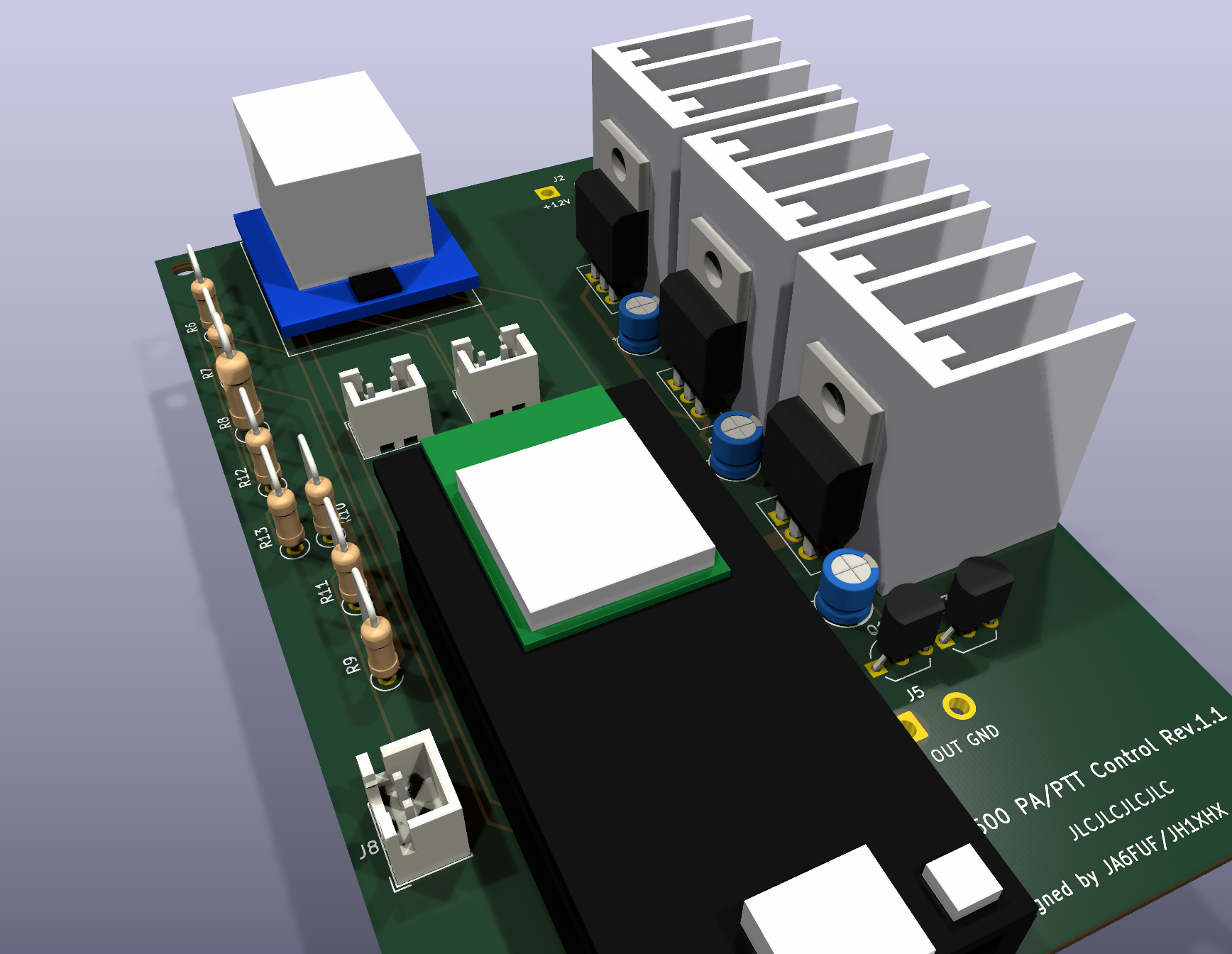
ESP32とW5500(有線LAN)で、PA等の12 V電源とPTTをLAN経由でON/OFFするオプションの制御基板。
使わなくてもShonan_Liteは動作する(PTTだけなら下記のPi 4 GPIO21で切替できる)。
ファームウェアはhardware/W5500_PA_PTT_Control/W5500_PA_PTT_Control.ino、
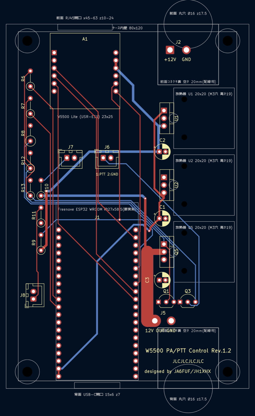
基板はhardware/W5500_PA_PTT_Control/kicad/(KiCad、Rev.1.0)。基板とファームウェアはShonan_Lite-RasPI5版と共通。
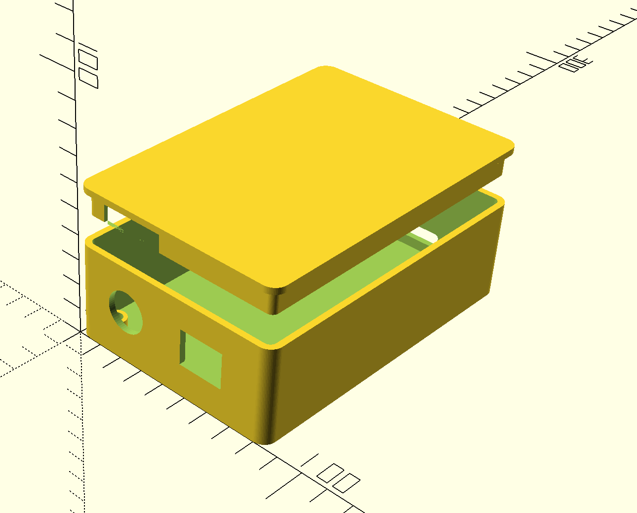
| 基板の3D表示 / 3D view of the board | 基板レイアウト(KiCad) / PCB layout (KiCad) | ケース(OpenSCAD) / Case (OpenSCAD) |
|---|---|---|
 |  |  |
| 項目 Item | 内容 Details |
|---|---|
| 構成 Configuration | Freenove ESP32-WROOM-32E DevKitC(ソケットに差し込み)+W5500 Lite(SPI接続) Freenove ESP32-WROOM-32E DevKitC (plugged into a socket) + W5500 Lite (SPI) |
| 12 V電源 12 V power | 2SJ334(Pチャネル MOSFET)のハイサイドスイッチでJ5の12 V出力をON/OFF。放熱器付きで目安は約7 Aまで J5's 12 V output is switched by a 2SJ334 (P-channel MOSFET) high-side switch; with its heatsink, up to about 7 A |
| PTT PTT | 2SC1815で無線機のPTT端子をGNDへ落とす(J6) A 2SC1815 pulls the radio's PTT line to GND (J6) |
| 電源入力 Power input | +12 V(13.8 V系)をJ2へ。L7805で5 V(ESP32)、TA48033Sで3.3 V(W5500)を作る +12 V (13.8 V class) to J2; an L7805 makes 5 V (ESP32) and a TA48033S makes 3.3 V (W5500) |
| 表示LED Indicator LEDs | 外付け。J7=12 V出力(赤)、J8=12 V入力(緑)(JST XH) External; J7 = 12 V output (red), J8 = 12 V input (green) (JST XH) |
| ネットワーク Network | 固定IP(初期値192.168.0.100)。ブラウザでhttp://<IP>/を開くと手動でON/OFFでき、http://<IP>/configでIPや遅延時間を変更できるStatic IP (default 192.168.0.100); open http://<IP>/ in a browser to switch ON/OFF manually, and http://<IP>/config to change the IP and delays |
| 基板 Board | 72×115 mm、4層(内層はGNDと+12Vのベタ)、部品はすべてスルーホール。JLCPCBの発注データはfabrication/jlcpcb/72×115 mm, 4 layers (inner layers are GND and +12 V planes), all through-hole parts. JLCPCB order data is in fabrication/jlcpcb/ |
| ケース Case | OpenSCAD(LAN_PTT.scad)、内寸80×120×35 mm。前面にRJ45の角穴と+12V入力の丸型コネクタ、背面にUSBの穴と12 V出力・PTTの丸型コネクタ OpenSCAD (LAN_PTT.scad), inside 80×120×35 mm. RJ45 opening and +12 V input circular connector on the front; USB opening and 12 V output/PTT circular connector on the back |
Shonan_Liteでの使い方:
詳しくは仕様書と
接続一覧を参照(どちらも日英併記。Word版・PDF版も同じフォルダにある)。
回路図: w5500-esp32.pdf、
実装図: w5500-esp32_実装図_部品番号.pdf。
[!NOTE] ESP32への書き込みと起動は確認済み。12 V電源・PTTの駆動回路と無線機をつないだ実地試験はまだ行っていない。
An optional control board that uses an ESP32 and a W5500 (wired LAN) to switch the 12 V power for the PA etc.
and the PTT ON/OFF over the LAN. Shonan_Lite works without it (PTT alone can be switched with the Pi 4 GPIO21 below).
The firmware is hardware/W5500_PA_PTT_Control/W5500_PA_PTT_Control.ino
and the board is in hardware/W5500_PA_PTT_Control/kicad/ (KiCad, Rev.1.0). The board and firmware are shared with the
Shonan_Lite-RasPI5 edition.
How to use it with Shonan_Lite:
For details, see the specification and the
connection list (both in Japanese and English;
Word and PDF versions are in the same folder).
Schematic: w5500-esp32.pdf;
assembly drawing: w5500-esp32_実装図_部品番号.pdf.
[!NOTE] Flashing and booting the ESP32 have been confirmed. A field test with the 12 V power/PTT drive circuits connected to a radio has not been done yet.
ESP32 W5500(PA_Power/PTTコントローラ、hardware/W5500_PA_PTT_Control)は
使わなくても、RasPI4からのPTT ON信号でPA・LNAの送受信切替を制御できる。
| 項目 Item | 内容 Details |
|---|---|
| 出力ピン Output pin | Pi 4 GPIO21(40番ピン)、GNDは39番ピン Pi 4 GPIO21 (pin 40), GND on pin 39 |
| 論理 Logic | 送信中HIGH(3.3 V)、受信中LOW HIGH (3.3 V) while transmitting, LOW while receiving |
| 対象 Applies to | Shonan_Liteの送信・Langstone V2Modifyの送信(Langstone標準のTx Output)のどちらも同じピン Both Shonan_Lite TX and Langstone V2Modify TX (Langstone's standard Tx Output) use the same pin |
pi4/gui/backend.pyの_set_pi_tx_gpio()、pinctrlで出力)。/tx?state=on|off)。12 V電源のON/OFFとホーム画面の「Pluto電源」カードはESP32 W5500が必要。
ESP32を使うかどうかは設定画面の「ESP32 W5500を使用する」で選ぶ(OFFにしてもIPアドレスは保持される)。The PA and LNA can be switched between TX and RX by the PTT ON signal from the RasPI4, even without the
ESP32 W5500 (PA_Power/PTT controller, hardware/W5500_PA_PTT_Control).
_set_pi_tx_gpio() in pi4/gui/backend.py, driven with pinctrl)./tx?state=on|off).
Switching the 12 V power ON/OFF and the "Pluto Power" card on the Home screen require the ESP32 W5500. Whether to use
the ESP32 is selected with "Use ESP32 W5500" on the Settings screen (the IP address is kept even when OFF).Home画面の「Langstone」カードから、kazushinjo/Langstone-V2Modify
(VHF/UHF/マイクロ波帯SDRトランシーバー、ADALM-Pluto対応)へ切り替えられる。
Langstone V2ModifyはQt eglfsとは別に/dev/fb0を直接描画する独立アプリのため、
DATV送受信アプリとは同時起動できない。shonan-gui.service/langstone.service/
shonan-boot-menu.serviceはsystemdのConflicts=で互いに排他制御されるため、
Pi4自体は再起動せず、サービスを直接切り替える。
切替時間を短くするため、切替のときはPluto+を再起動しない(Pi5版で、再起動しなくても両アプリの
送受信が正常に動くことを確認済み)。ただしLangstoneは受信中に送信LOを止めたまま終了するため、
戻るときはLangstone側・Shonan_Lite側の両方で送信LOを元に戻す。Shonan_Liteは起動時(電源投入時を含む)に
Pluto+を再起動しない(ホーム画面の「アプリ再起動」と、Langstoneを「GOTO SHONAN_LITE」以外で終了したときは再起動する)。
Langstone側は/tmp/langstone_goto_shonan、Shonan_Lite側は/tmp/shonan_switch_from_langstone
の印で切替かどうかを判断する。
Langstone V2Modify is a standalone app that draws directly to /dev/fb0 separately from Qt eglfs, so it cannot run at
the same time as the DATV app. shonan-gui.service, langstone.service and shonan-boot-menu.service are mutually
exclusive through systemd's Conflicts=, so the services are switched directly without rebooting the Pi 4.
To shorten the switching time, the Pluto+ is not rebooted when switching (confirmed on the Pi 5 version that both apps
transmit and receive normally without a reboot). However, Langstone exits with the TX LO powered down while receiving,
so the TX LO is restored on both the Langstone side and the Shonan_Lite side when returning. Shonan_Lite does not
reboot the Pluto+ when it starts (including at power-up); it is rebooted by "App Restart" on Home and when Langstone
exits other than via "GOTO SHONAN_LITE".
The Langstone side uses the /tmp/langstone_goto_shonan marker and the Shonan_Lite side uses
/tmp/shonan_switch_from_langstone to tell whether it is a switch.
内部的には~/.pi4_boot_mode_langstoneマーカーファイルの有無をsystemdの
ConditionPathExistsで判定し、shonan-gui.service/langstone.serviceの
どちらを起動すべきかを決める。
Internally, systemd's ConditionPathExists checks for the ~/.pi4_boot_mode_langstone marker file to decide whether
shonan-gui.service or langstone.service should start.
ウォーターフォール/スペクトラム表示は幅約512px→約790pxへ拡張済み
(FFT点数自体はGNU Radio側のfft_size=512のまま、SCALEPX()マクロで描画のみ
引き伸ばしている。帯域インジケータ・目盛り・タッチ判定も含め一貫して変換)。
横方向にはSQLボタン(x=30〜130)/Volボタン(x=660〜)と同じY帯で重なり広げる
余地が無かったため、スペクトラム欄の高さ(80→55px)とウォーターフォールの
表示履歴行数(130→90行)を縮めて表示位置を上に詰め、SQL/Vol/RITいずれとも
Y方向に重ならない帯(Y=130〜295)に収めることで横方向をほぼ画面全幅まで
広げた(実機で確認)。
統合元はkazushinjo/Langstone-V2Modifyで、Pi 4 + DFRobot DFR0550 +
ADALM-Pluto向けの修正を含む。
The waterfall/spectrum display has been widened from about 512 px to about 790 px (the number of FFT points stays at
fft_size=512 on the GNU Radio side; only the drawing is stretched by the SCALEPX() macro, applied consistently to the
bandwidth indicator, scale and touch detection). Since there was no room to widen it horizontally in the same Y band as
the SQL button (x=30–130) and Vol button (x=660–), the spectrum area height (80 → 55 px) and the number of waterfall
history rows (130 → 90) were reduced and the display moved up into a band (Y=130–295) that does not overlap SQL/Vol/RIT
vertically, which allows it to extend to nearly the full screen width (confirmed on the device). It is integrated from
kazushinjo/Langstone-V2Modify and includes fixes for the Pi 4 + DFRobot DFR0550 + ADALM-Pluto.
kazushinjo/Langstone-V2Modifyが更新された場合は、
pi4/scripts/update_langstone_from_upstream.sh
で同梱コピーを更新できる。更新後はShonan切替用のマーカー処理・受信専用バンド(bandRxOnly)など、
統合固有の差分を確認してから使用すること。
When kazushinjo/Langstone-V2Modify is updated, the bundled copy can be updated with
pi4/scripts/update_langstone_from_upstream.sh.
After updating, check the integration-specific differences, such as the Shonan switching markers and the receive-only
band (bandRxOnly), before use.
Home画面の背景右側の衛星をタップすると、Langstone V2Modifyを10GHz受信用のバンドで 開く(普通の「Langstone」カードと同じく、Plutoは再起動しない)。アンテナ側で LNB(局部発振9750 MHz)を使い、10 GHz帯を486.5 MHzへ下げて受信する前提。
Tapping the satellite on the right side of the Home screen background opens Langstone V2Modify on a band for 10 GHz reception (as with the normal "Langstone" card, the Pluto is not rebooted). This assumes an LNB (local oscillator 9750 MHz) on the antenna side that converts the 10 GHz band down to 486.5 MHz.
| 項目 Item | 値 Value |
|---|---|
| 画面の表示周波数 Displayed frequency | 10236.500 MHz(10.2365 GHz) 10236.500 MHz (10.2365 GHz) |
| Plutoの受信周波数 Pluto receive frequency | 486.5 MHz(= 10236.5 − 9750) |
| 受信オフセット Receive offset | −9750 MHz(LNB 局部発振 9750 MHz) −9750 MHz (LNB local oscillator 9750 MHz) |
| 送信 Transmit | 不可(受信専用) Not possible (receive only) |
~/Langstone/Langstone_Pluto.conf
のこのバンドを上の値に設定し直してから開く(pi4/gui/langstone_config.py)。bandRxOnly23 1、Langstone側の改造)。画面のPTT・ハードウェアPTT・
CWキー・ビーコンのいずれでも送信せず、PA_Power/PTTコントローラも送信に切り替えない。
PTTボタンは灰色の「RX ONLY」表示になり、Plutoの送信LOも停止させる。~/Langstone/Langstone_Pluto.conf to the values
above before opening (pi4/gui/langstone_config.py).bandRxOnly23 1 in the configuration
file, a modification on the Langstone side). It does not transmit from the on-screen PTT, hardware PTT, CW key or
beacon, and does not switch the PA_Power/PTT controller to transmit. The PTT button is shown grayed out as "RX ONLY",
and the Pluto's TX LO is also stopped.pi4/docs/install_script_guide.md — install.shの詳細ガイド / Detailed guide to install.sh(英語版 / English: install_script_guide_en.md)pi4/docs/qtvirtualkeyboard_ja_build.md — 日本語オンスクリーンキーボードのビルド手順・ハマりどころ / Build steps and pitfalls for the Japanese on-screen keyboardpi4/docs/shonan_pi4_operation_manual.docx / pi4/gui/manual_content.py — GUIの操作説明書(アプリ内Helpと同内容。英語のHelpはpi4/gui/screens/manual.py) / Operation manual for the GUI (same content as the in-app Help; the English Help is in pi4/gui/screens/manual.py)pi4/docs/build_operation_manual.py — 操作説明書(DOCX)の生成スクリプト(python pi4/docs/build_operation_manual.py、python-docxが必要) / Script that generates the operation manual (DOCX) (requires python-docx)hardware/W5500_PA_PTT_Control/docs/W5500_PA_PTT_Control_仕様書.md — ESP32 W5500(PA_Power/PTTコントローラ)の仕様書 / Specification of the ESP32 W5500 (PA_Power/PTT controller)(日英併記 / Japanese and English)
hardware/W5500_PA_PTT_Control/docs/tools/build_docs.pyでMarkdownから作る(macOSで実行) / The Word and PDF versions of the specification and connection list are generated from Markdown with this script (run on macOS)hardware/W5500_PA_PTT_Control/docs/MCU1_J1_W5500_接続一覧.md — ESP32・W5500の接続一覧 / Connection list of the ESP32 and W5500(日英併記 / Japanese and English)hardware/W5500_PA_PTT_Control/kicad/ — ESP32 W5500制御基板のKiCad回路図・基板 / KiCad schematic and PCB of the ESP32 W5500 control boardpi4/third_party/rpi-dvbs2-receiver-gui/ — GNU Radio/gr-dvbs2rx受信フローグラフの参考実装(kazushinjo/rpi-dvbs2-receiver-guiより取り込み) / Reference implementation of the GNU Radio/gr-dvbs2rx receive flowgraph (imported from kazushinjo/rpi-dvbs2-receiver-gui)kazushinjo/Langstone-V2Modifyを
pi4/third_party/Langstone-V2Modify/に同梱)kazushinjo/Langstone-V2Modify, modified for the Pi 4 + DFRobot DFR0550 +
ADALM-Pluto, is bundled in pi4/third_party/Langstone-V2Modify/)本ソフトウェアはGNU General Public License v3.0(GPLv3)の下で提供されます。 ライセンス全文: LICENSE
This software is licensed under the GNU General Public License v3.0 (GPLv3). Full license text: LICENSE
kazushinjo/Langstone-V2Modify): GPLv3| Qty | Value | Footprint | References |
|---|---|---|---|
| 3 | 0.01 | Capacitor_THT:C_Disc_D4.3mm_W1.9mm_P5.00mm | C1, C5, C6 |
| 3 | Conn_01x02_Female | Connector_Molex:Molex_KK-254_AE-6410-02A_1x02_P2.54mm_Vertical | J1, J2, J3 |
| 2 | 1K | Resistor_THT:R_Axial_DIN0207_L6.3mm_D2.5mm_P5.08mm_Vertical | R2, R3 |
| 2 | 1mH | Inductor_THT:L_Radial_D10.5mm_P5.00mm_Abacron_AISR-01 | L1, L2 |
| 2 | 330u | Capacitor_THT:CP_Radial_D8.0mm_P5.00mm | C2, C3 |
| 2 | MountingHole | MountingHole:MountingHole_3.2mm_M3 | H3, H4 |
| 2 | MountingHole_Pad | MountingHole:MountingHole_2.5mm_Pad | H1, H2 |
| 1 | 1.8K | Resistor_THT:R_Axial_DIN0207_L6.3mm_D2.5mm_P5.08mm_Vertical | R1 |
| 1 | 100 | Capacitor_THT:CP_Radial_D6.3mm_P2.50mm | C4 |
| 1 | 1N4448 | Diode_THT:D_DO-35_SOD27_P7.62mm_Horizontal | D1 |
| 1 | Conn_01x04_Female | Connector_Molex:Molex_KK-254_AE-6410-04A_1x04_P2.54mm_Vertical | J4 |
| 1 | TLP222A-2 | Package_DIP:DIP-8_W7.62mm | U1 |

kazushinjo/Shonan_Lite-RasPI5
DATV Tranceiver Shonan_Lite for Raspberry Pi 5 with Langstone-V3Modify + Pluto v0.32-dirty

jer-lil/tremolo-hardware
This is the hardware (PCB, MCAD) design for a tremolo pedal for guitar (or bass, synth, tonewheel organ, whatever you like). The firmware is here: https://github.com/jer-lil/tremolo-firmware/tree/main

gusmanb/logicanalyzer
24 channel, 100Msps logic analyzer hardware and software

mntmn/amiga2000-gfxcard
MNT VA2000, an Open Source Amiga 2/3/4000 Graphics Card (Zorro II/III), written in Verilog


hackclub/OnBoard
💡 Join 1,000 teenagers and make your first PCB with a $100 grant!

drandyhaas/KiCadRoutingTools
A set of Python/Rust tools to aid routing in KiCad
It measures 57.3 × 49 mm and has 2 copper layers, 1.6 mm thick.
21 parts, built around the TLP222A-2(F). The full list of its parts is on this page, with links to each part's symbol and footprint where PCBKit's library has them.
From the kazushinjo/Shonan_lite-PI4 repository on GitHub, at the commit this page was made from: the board is hardware/audio-ptt-control/kicad/audio-ptt-control.kicad_pcb and its schematic hardware/LangStonePower/LangStonePower.kicad_sch. PCBKit opens the board in the browser, with nothing to install.
Its repository states no licence, so its author keeps all rights: ask kazushinjo before reusing the design.