2 layers28.3 × 39.8 mm
LevelShifter
gusmanb/logicanalyzer
24 channel, 100Msps logic analyzer hardware and software
21 parts5.1kGPL-3.0

 kareiva/micromodem-pcb2
MicroModem-compatible PCB shield for Arduino Nano by LY2EN
LY2EN micromodem is an open-source printed circuit board by kareiva, from the kareiva/micromodem-pcb repository on GitHub. It is a 2-layer board of 20.4 × 68.1 mm with 21 parts on 35 nets, routed with 102 tracks and 5 vias.
Its parts include 12 resistors, 3 capacitors and 1 transistor. It belongs with the AVR (ATmega, ATtiny) boards of this library.
PCB and schematics for a very basic MicroModem shield for Arduino Nano to use with Baofeng radios.
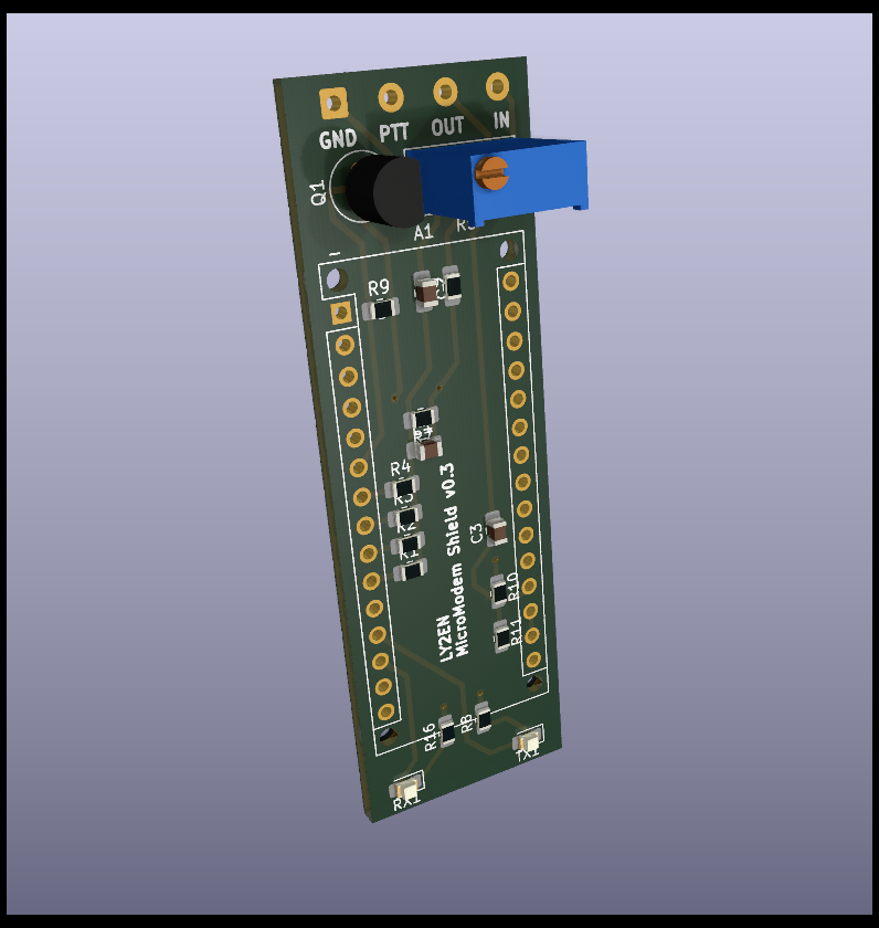
This is experimental work. The authors do not hold any responsibility for any damage to your electronics components, wiring or other property when using this prototype. Use at your own risk.
Upload the MicroAPRS 3v KISS firmware to the Arduino Nano:
avrdude -p m328p -c arduino -P /dev/ttyUSB0 -b 115200 -U flash:w:microaprs-3v-kiss-latest.hex
Plug the Arduino Nano into your Android phone's USB host
Launch APRSDroid
3.1 Select TNC (KISS) mode over USB.
3.2 Keep the baud rate at 9600.
Set the 3296W trimmer to something around 47kOhm. Your resistance might vary here. Once you're confident, you can replace it with a simple 47k resistor.
Verified working with both the MicroAPRS KISS and MicroAPRS SimpleSerial firmware for 3V.
If you're not using a Bluetooth SPP-C module, a USB-C male to USB-A female adapter is required for recent Android smartphones.
Connect to Baofeng radio over this cable.
The Baofeng cable has two TRS (Tip, Ring, Sleeve) connectors.
PCB made by Simonas Kareiva LY2EN (ly2en@qrz.lt) using KiCad and by looking at the original schematics.
Inspiration by Vilius LY3FF.
MicroModem originally by https://github.com/markqvist
| Qty | Value | Footprint | References |
|---|---|---|---|
| 3 | 1k | Resistor_SMD:R_0805_2012Metric_Pad1.20x1.40mm_HandSolder | R1, R6, R16 |
| 2 | 100k | Resistor_SMD:R_0805_2012Metric_Pad1.20x1.40mm_HandSolder | R10, R11 |
| 2 | 270 | Resistor_SMD:R_0805_2012Metric_Pad1.20x1.40mm_HandSolder | R7, R8 |
| 2 | LED | LED_SMD:LED_0805_2012Metric_Pad1.15x1.40mm_HandSolder | RX1, TX1 |
| 1 | 100nF | Capacitor_SMD:C_0805_2012Metric_Pad1.18x1.45mm_HandSolder | C1 |
| 1 | 10k | Resistor_SMD:R_0805_2012Metric_Pad1.20x1.40mm_HandSolder | R9 |
| 1 | 1uF | Capacitor_SMD:C_0805_2012Metric_Pad1.18x1.45mm_HandSolder | C3 |
| 1 | 2N7000 | Package_TO_SOT_THT:TO-92_Inline | Q1 |
| 1 | 2k2 | Resistor_SMD:R_0805_2012Metric_Pad1.20x1.40mm_HandSolder | R2 |
| 1 | 3k9 | Resistor_SMD:R_0805_2012Metric_Pad1.20x1.40mm_HandSolder | R3 |
| 1 | 4.7uF | Capacitor_SMD:C_0805_2012Metric_Pad1.18x1.45mm_HandSolder | C2 |
| 1 | 47k | Resistor_SMD:R_0805_2012Metric_Pad1.20x1.40mm_HandSolder | R5 |
| 1 | 8k2 | Resistor_SMD:R_0805_2012Metric_Pad1.20x1.40mm_HandSolder | R4 |
| 1 | Arduino_Nano_Every | Module:Arduino_Nano_WithMountingHoles | A1 |
| 1 | BT_MOD | Connector_PinSocket_2.54mm:PinSocket_1x05_P2.54mm_Vertical | Conn_01x5 |
| 1 | SolderWire | Connector_Wire:SolderWire-0.5sqmm_1x04_P4.6mm_D0.9mm_OD2.1mm | _ |
gusmanb/logicanalyzer
24 channel, 100Msps logic analyzer hardware and software

mntmn/amiga2000-gfxcard
MNT VA2000, an Open Source Amiga 2/3/4000 Graphics Card (Zorro II/III), written in Verilog


hackclub/OnBoard
💡 Join 1,000 teenagers and make your first PCB with a $100 grant!

drandyhaas/KiCadRoutingTools
A set of Python/Rust tools to aid routing in KiCad

Arrow-air/project-quiver
Project Quiver documentation, designs, and project artifacts.


It measures 20.4 × 68.1 mm and has 2 copper layers, 1.6 mm thick.
21 parts. The full list of its parts is on this page, with links to each part's symbol and footprint where PCBKit's library has them.
From the kareiva/micromodem-pcb repository on GitHub, at the commit this page was made from: the board is LY2EN-micromodem.kicad_pcb and its schematic LY2EN-micromodem.kicad_sch. PCBKit opens the board in the browser, with nothing to install.
Its repository states no licence, so its author keeps all rights: ask kareiva before reusing the design.