2 layers158 × 11 mm
Daylight Matchstick
VoronDesign/Voron-Hardware
Cool Hardware designed by the Voron Design group
22 parts1.1kGPL-3.0

 kallioderso/Copy-Paste-Pad
A Micropad, designed to provide multiple Copy Paste Keys to store multiple Texts on your Computer at the same time
Copy Paste Pad is an open-source printed circuit board by kallioderso, from the kallioderso/Copy-Paste-Pad repository on GitHub. It is a 2-layer board of 69 × 82 mm with 22 parts on 22 nets, routed with 102 tracks and 8 vias.
Its parts include 8 diodes, 8 switches and 2 ICs.
a Short Keyboard with 8 Keys, 8 Diodes, a small OLED screen and an Seeed XIAO RP2040 on board. Developed for the purpose of unlocking the possibility to store up to 6 different Texts or other Things inside the memory, while keeping an overview and controlled usage of the stored elements.
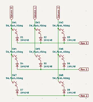
The Board was deisgned in KiCAD as first of this kind experience for myself and included the mentioned Seeed XIAO RP2040. There i connected the 8 Keys and theire 8 Diodes inside a 3 x 3 Key Matrix, as shown in a youtube tutorial by ai03.
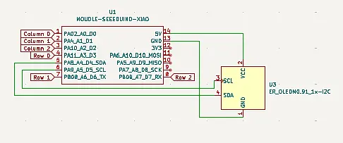
Apart from that i Added as wel a OLED screen to show wheather the Keyboard is currently in a Copy or a Paste state or if both false, in an displaying state. The OLED Screen is currently wired with the 5V output of the Seeed XIAO RP2040, but might be later reduced to the 3.3V output. Apart from that its wired with the GNU which i learned, is to remove electicity from components, so the opposit of the Voltage outputs. Last but not Least is the OLED screen wired with the SDA and SCL pins.
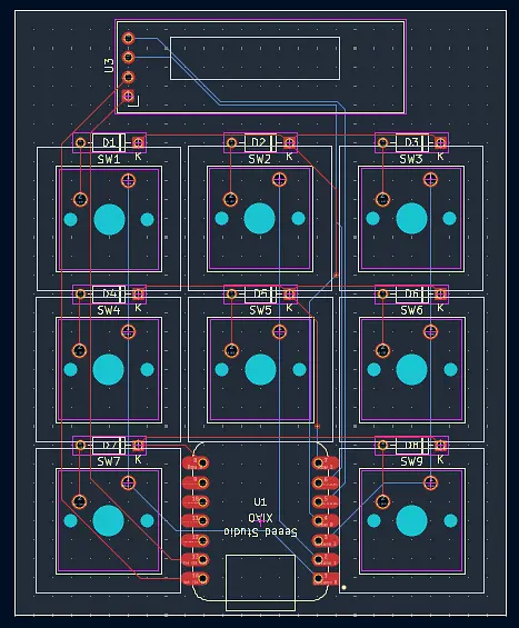
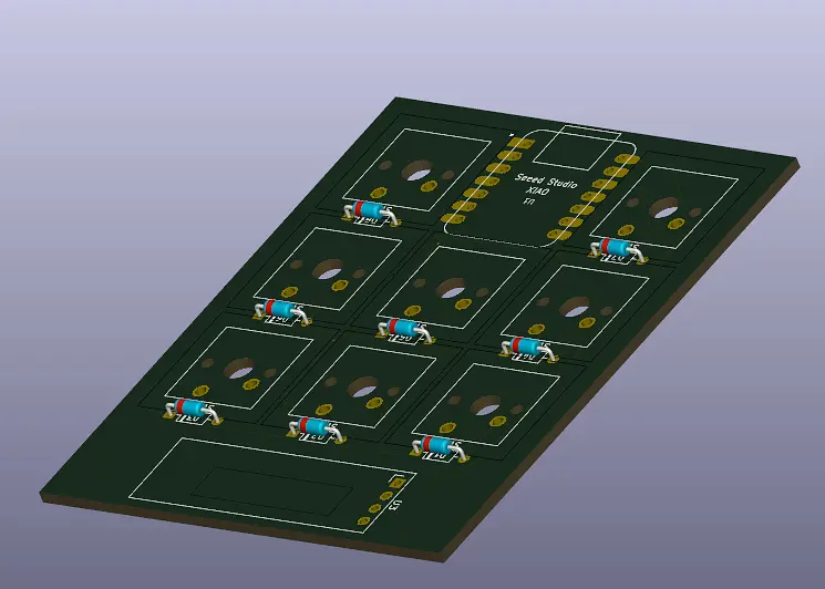
In The following you can than see the finished PCB inside KiCAD, as well as its 3D Rendering. Sadly i wasnt able to render the Seeed XIAO RP2040 and the 8 Keys, but at least the 8 Diodes -_- .
The Casing is one of the most important things of an Keyboard, as it determines wheather a Product will be loved or hated by an Community. but anyways did i keep a relativly simple design with rounded edges and a simple but effectiv order of the different keys and the OLED screen. In the following you can see first, the Bottom of the Casing, and after that the top, which later on will get fixed into the bottom half.
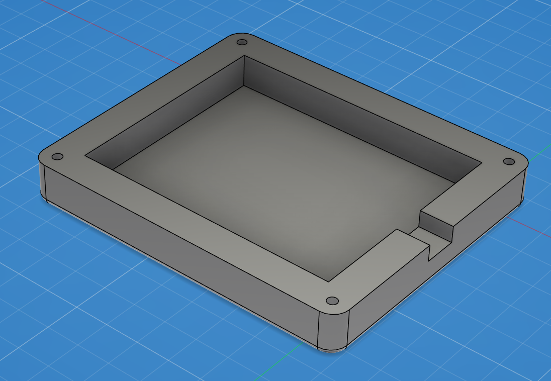
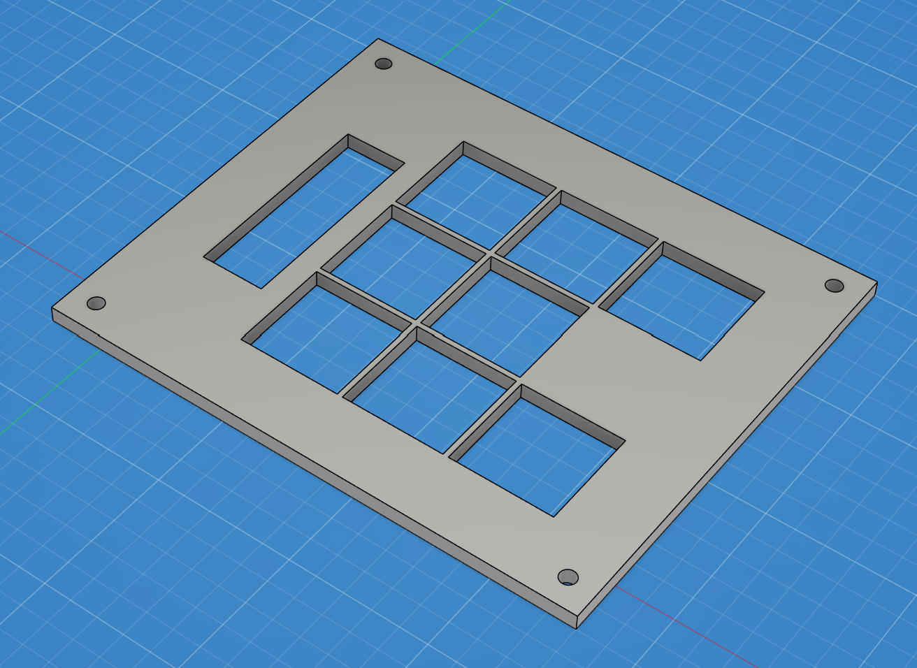
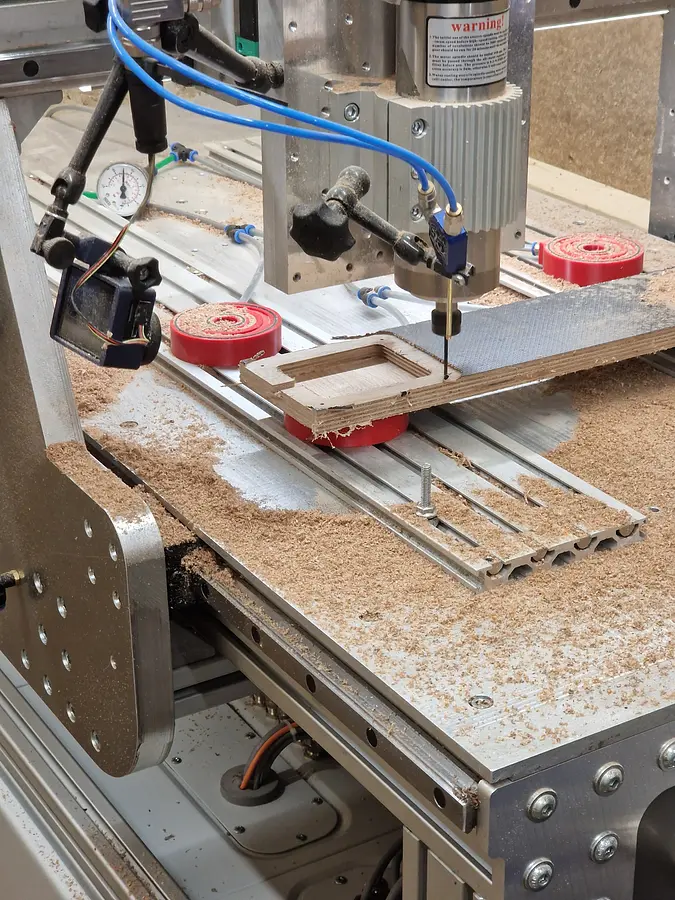
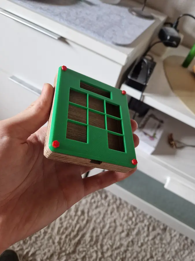
as wood is a great material, appearing in high quality and therefore more professional i as well created the entire bottom half of the casing as .dxf just as the top part, which unfortunatly could just be made by a laser, as a CNC machine would struggle with the fine borders beetwheen each key switch.
besides all the hardware, the firmware is what makes a product standing out from others, therefore the mission was clear. 1 key to activate the so called copying mode, one other key to activate the pasting mode. both of which would stay active until you decide to deactivate them.
so the only remaining thing would be to press the wanted key switch for the different (out of 6) clipboards.
to achieve this the keyboard needs both, a own firmware. as well as a .exe Application running on the PC himself to performe all the Copying and Pasting things the keyboard itself isnt allowed.
the QMK firmware consists of the v1 keymap, presenting almost every smart thing and function in general provided by the keyboard. this gets underlined by the rules set to make working with hid (human interface device) and the OLED screen possible.
Last but not least is there the keyboard info providing every basic information about the producer, its components and the key matrix, consisting of Rows and Columns
the Womdpws Application in form of an .exe is where the fun begins. it gets hid (human interface device) signals by the QMK firmware, telling it what action to performe.
Whether its Copying, Pasting or just doing nothing, the hid is the source of decision.
to prevent the user from having to start this Script each time they start their PCs, it is so smart that it writes itself into the Auto start after the first execution of itself. making it possible to use the keyboard without any action.
| Qty | Value | Footprint | References |
|---|---|---|---|
| 8 | 1N4148 | Diode_THT:D_DO-35_SOD27_P7.62mm_Horizontal | D1, D2, D3, D4, D5, D6, D7, D8 |
| 8 | SW_Push_45deg | Button_Switch_Keyboard:SW_Cherry_MX_1.00u_PCB | SW1, SW2, SW3, SW4, SW5, SW6, SW7, SW9 |
| 4 | MountingHole_Pad | MountingHole:MountingHole_3.2mm_M3 | H1, H2, H3, H4 |
| 1 | ER_OLEDM0.91_1x-I2C | Display:ER_OLEDM0.91_1x-I2C | U3 |
| 1 | MOUDLE-SEEEDUINO-XIAO | footprints:XIAO-Generic-Hybrid-14P-2.54-21X17.8MM | U1 |
VoronDesign/Voron-Hardware
Cool Hardware designed by the Voron Design group

hoglet67/RGBtoHDMI
Bare-metal Raspberry Pi project that provides pixel-perfect sampling of Retro Computer RGB/YUV video and conversion to HDMI

hackclub/OnBoard
💡 Join 1,000 teenagers and make your first PCB with a $100 grant!

abhishek-kakkar/BeagleLogic
A Software Suite that implements a logic analyzer with the PRU on the BeagleBone / BeagleBone Black.

Chrismettal/flipper-zero-backpacks
Backpack-style addon boards for the Flipper Zero!


CRImier/MyKiCad
My KiCad boards. Can't be bothered uploading individually anymore, so here you go.
It measures 69 × 82 mm and has 2 copper layers, 1.6 mm thick.
22 parts. The full list of its parts is on this page, with links to each part's symbol and footprint where PCBKit's library has them.
From the kallioderso/Copy-Paste-Pad repository on GitHub, at the commit this page was made from: the board is PCB/Copy-Paste-Pad.kicad_pcb and its schematic PCB/Copy-Paste-Pad.kicad_sch. PCBKit opens the board in the browser, with nothing to install.
Its repository states no licence, so its author keeps all rights: ask kallioderso before reusing the design.