2 layers39 × 60.3 mm
Analisador Bode
LuizFernandoOliveira/Analisador_Bode
This work is licensed under a [Creative Commons Attribution-NonCommercial-NoDerivs 4.0 International License][cc-by-nc-nd].
64 parts

 kaitallaoua/capstone-pcb1
In collaboration with the University of Saskatchewan, we are contributing a payload board for the CubeSats Initiative in Canada for STEM (CUBICS).
Mcu integration is an open-source printed circuit board by kaitallaoua, from the kaitallaoua/capstone-pcb repository on GitHub, published under the GPL-3.0 licence. It is a 4-layer board of 90.2 × 95.9 mm with 110 parts on 236 nets, routed with 688 tracks and 221 vias.
It is built around the TL081IDT, UA78M33CDCYG3 and ECS-80-18-5PX-GM-TR. Its parts include 45 capacitors, 34 resistors, 15 ICs, 3 connectors and 1 diode. It belongs with the STM32 boards of this library.


In collaboration with the University of Saskatchewan, we are contributing a payload board for the CubeSats Initiative in Canada for STEM (CUBICS). A CubeSat is a low cost, small and approachable design for students “to engage in an end-to-end space mission adapted to their needs and their level of comfort, expertise and readiness” (asc-csa. gc.ca). Our payload studies the effects of space radiation on commonly used surface mount analog Integrated Circuits (IC’s) in Low Earth Orbit (LEO). We compare different shielding to see which provides a better effectiveness to weight ratio.

Available here
This project used KiCad Version: 7.0.11-7.0.11~ubuntu22.04.1, release build and a mix of windows builds.
Download KiCad here. KiCad 8 likely does work and I recommend you use it.
TBD (remove this once done): Someone needs to fork this repo to make further contributions to the project. Using an organization is best, I think UofS space team has one, maybe Regina team should make one? Regardless I will not be reviewing and accepting PR's to this repo.
Because using git for KiCad is like tracking binary files, I recommend to NOT rely on git handling merge conflicts. Avoid them entirely by letting only one person make changes on one branch at a time, make a PR, approve and merge and repeat and pass the baton to someone else to make changes.
The most substantial changes the sinwave generation. This task was assigned to Evan. Ultimately we could not get it working, thus I recommend to use a PWM wave gen from the mcu, likely add pre-amplification + current buffering, and pass it to a sharp drop off filter. The filter could be a dedicated one (probably better) or an op-amp driven one (butterworth?, wont have as good drop off without many stages).
UofRobotics is also making a PCB for their robot whose base is forked from this project, they may be a good reference for questions or idea sharing.
We used JLCPCB for REV A and REV B with great results. We also have nearly all parts ready for another revision. AT LEAST ONE MORE REVISION IS NEEDED SINCE THE FOLLOWING WERE FIXED AFTER REV B:
Our manufacturing procedure was as follows:
Order from JLC (1 week delivery), Order from Mouser/Digikey (2-4 day delivery) -> Have all parts -> Go to ED435, use microscope, have one person assist finding parts, one pick+place, apply solder paste (min 4-5 hours)-> place in oven -> done
I recommend to use the parts list available from JLCPCB or PCBWay to assemble as much of the board for you as possible, it saves alot of time but honestly building it by hand it also not that bad. Either is fine.
KiCad 6 STM32 PCB Design Full Tutorial - Phil's Lab #65
PCB Design Final Touches (Tips & Checklist) - Phil's Lab #131
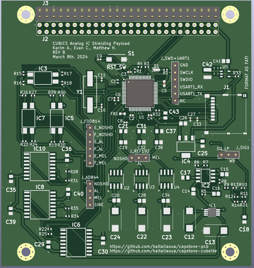
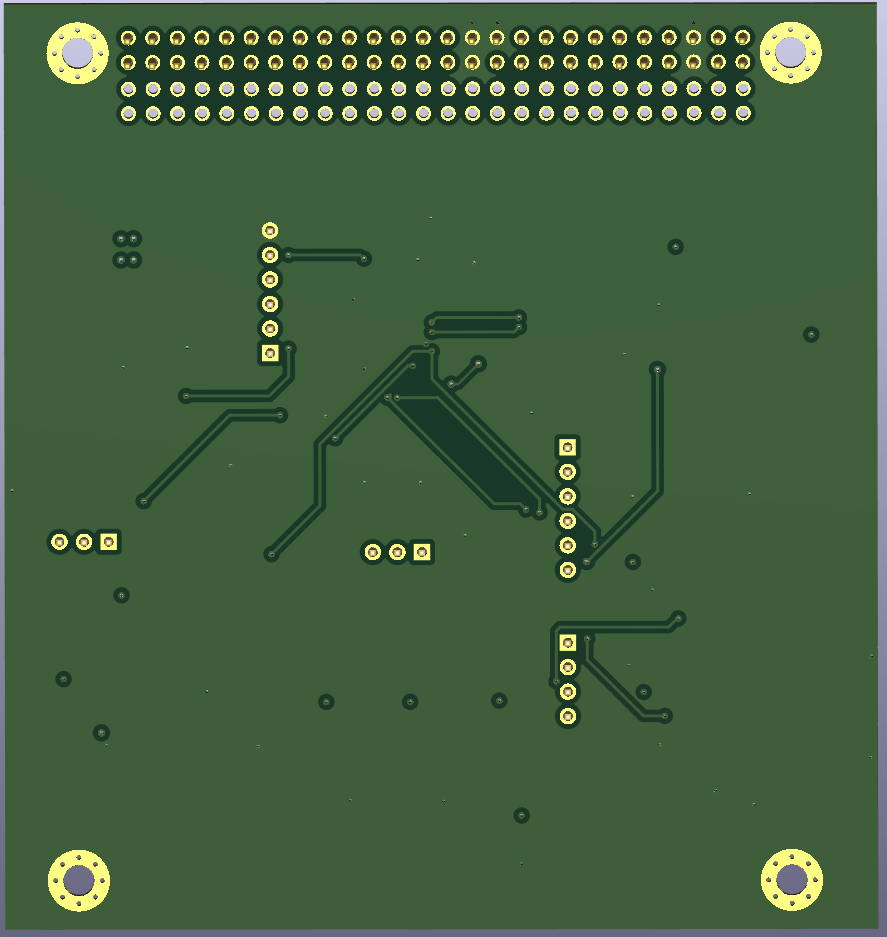
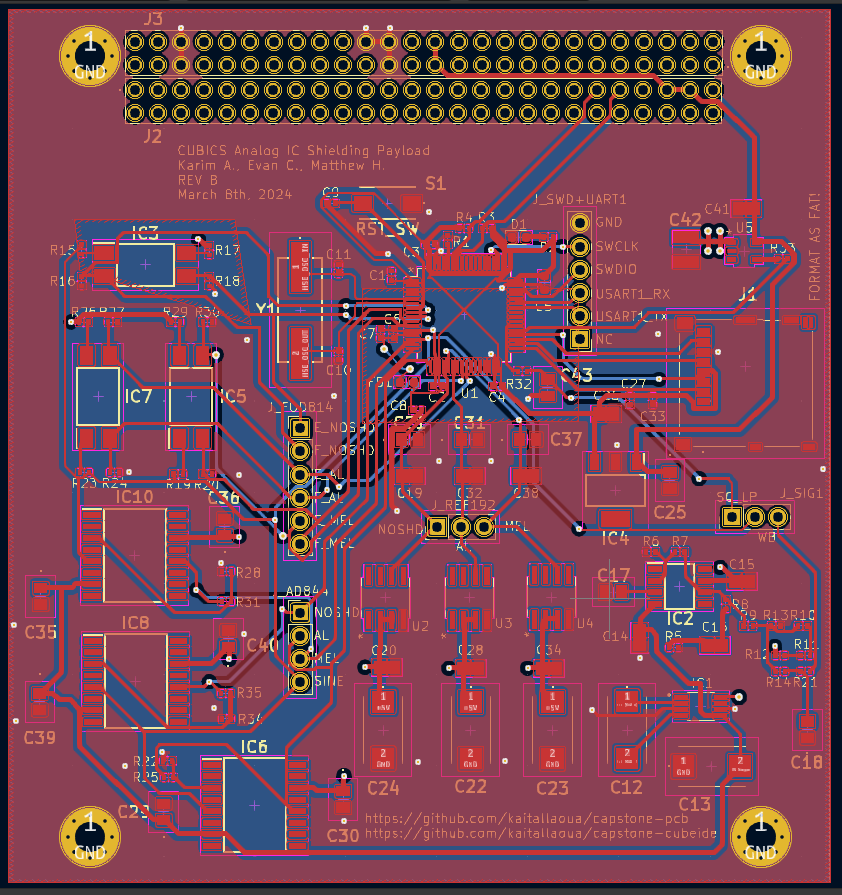
| Qty | Value | Footprint | References |
|---|---|---|---|
| 12 | 0.1u | capstone:CAPC220145_88N_KEM-0.1u | C14, C15, C19, C20, C26, C28, C32, C34, C38, C41, C44, C45 |
| 6 | 0.22u | capstone:C0805-0.22u | C29, C30, C35, C36, C39, C40 |
| 6 | 100 | Resistor_SMD:R_0402_1005Metric | R17, R18, R26, R27, R29, R30 |
| 6 | 100k | Resistor_SMD:R_0402_1005Metric | R5, R6, R8, R22, R28, R34 |
| 6 | 100n | Capacitor_SMD:C_0402_1005Metric | C2, C3, C4, C6, C9, C27 |
| 5 | 10u | capstone:T495D | C12, C13, C22, C23, C24 |
| 4 | 2.2k | Resistor_SMD:R_0402_1005Metric | R1, R2, R3, R4 |
| 4 | MountingHole_Pad | MountingHole:MountingHole_3.2mm_M3_Pad_Via | H1, H2, H3, H4 |
| 3 | 0.01u | capstone:C0805 | C17, C18, C43 |
| 3 | 1k | Resistor_SMD:R_0402_1005Metric | R25, R31, R35 |
| 3 | 1u | capstone:C0805-1u | C21, C31, C37 |
| 3 | 1u | Capacitor_SMD:C_0402_1005Metric | C7, C8, C33 |
| 3 | 47 | Resistor_SMD:R_0402_1005Metric | R16, R20, R24 |
| 3 | 820 | Resistor_SMD:R_0402_1005Metric | R15, R19, R23 |
| 2 | 1.8k | Resistor_SMD:R_0402_1005Metric | R9, R11 |
| 2 | 20p | Capacitor_SMD:C_0402_1005Metric | C10, C11 |
| 2 | 56k | Resistor_SMD:R_0402_1005Metric | R14, R32 |
| 2 | Conn_01x03 | Connector_PinHeader_2.54mm:PinHeader_1x03_P2.54mm_Vertical | J_REF192, J_SIG1 |
| 2 | Conn_01x06 | Connector_PinHeader_2.54mm:PinHeader_1x06_P2.54mm_Vertical | J_FOD814, J_SWD+UART1 |
| 2 | ESQ-126-39-L-D | capstone:ESQ-126-Y-X-D | J2, J3 |
| 2 | TL081IDT | capstone:SOIC127P600X175-8N | IC2, IC9 |
| 1 | 0.01u | capstone:CAPC220145_88N_KEM-0.1u | C16 |
| 1 | 0.33u | capstone:C0805 | C25 |
| 1 | 1.0k | Resistor_SMD:R_0402_1005Metric | R10 |
| 1 | 100n | Resistor_SMD:R_0402_1005Metric | C1 |
| 1 | 10u | Capacitor_SMD:C_0603_1608Metric | C5 |
| 1 | 12k | Resistor_SMD:R_0402_1005Metric | R13 |
| 1 | 150u | capstone:CAPC3225X280N_150U | C42 |
| 1 | 200 | Resistor_SMD:R_0402_1005Metric | R33 |
| 1 | 220k | Resistor_SMD:R_0402_1005Metric | R7 |
| 1 | 330 | Resistor_SMD:R_0402_1005Metric | R12 |
| 1 | AD844_OPAMP_AL | capstone:SOIC127P1032X265-16N-AD844 | IC6 |
| 1 | AD844_OPAMP_MEL | capstone:SOIC127P1032X265-16N-AD844 | IC10 |
| 1 | AD844_OPAMP_NOSHD | capstone:SOIC127P1032X265-16N-AD844 | IC8 |
| 1 | Conn_01x04 | Connector_PinHeader_2.54mm:PinHeader_1x04_P2.54mm_Vertical | J_AD844 |
| 1 | ECS-80-18-5PX-GM-TR | capstone:ECS80185PXGMTR | Y1 |
| 1 | FOD814_OPTO_AL | capstone:SOP254P1016X385-4N-FOD | IC7 |
| 1 | FOD814_OPTO_MEL | capstone:SOP254P1016X385-4N-FOD | IC5 |
| 1 | FOD814_OPTO_NOSHD | capstone:SOP254P1016X385-4N-FOD | IC3 |
| 1 | FerriteBead | Inductor_SMD:L_0603_1608Metric | FB1 |
| 1 | Micro_SD_Card | capstone:22017781 | J1 |
| 1 | RED | LED_SMD:LED_0603_1608Metric | D1 |
| 1 | REF192_AL | capstone:R_8_ADI-REF | U3 |
| 1 | REF192_MEL | capstone:R_8_ADI-REF | U4 |
| 1 | REF192_NOSHD | capstone:R_8_ADI-REF | U2 |
| 1 | RST_SW | capstone:95C04A3GWRT | S1 |
| 1 | STM32F103RBTx | Package_QFP:LQFP-64_10x10mm_P0.5mm | U1 |
| 1 | TL7660IDGKR | capstone:SOP65P490X110-8N-actual | IC1 |
| 1 | TPS2069CDBVR_MOSFET | capstone:DBV5_TEX_MF | U5 |
| 1 | UA78M33CDCYG3 | capstone:SOT230P700X180-4N | IC4 |
LuizFernandoOliveira/Analisador_Bode
This work is licensed under a [Creative Commons Attribution-NonCommercial-NoDerivs 4.0 International License][cc-by-nc-nd].


Neumi/ethersweep
Open Source, easy to use Ethernet connected stepper motor controller. Built in FreeCAD, KiCAD and Arduino.


mark-belbin/motor-controller
Custom FOC motor controller designed for underwater robotics.

It measures 90.2 × 95.9 mm and has 4 copper layers, 1.6 mm thick.
110 parts, built around the TL081IDT, UA78M33CDCYG3 and ECS-80-18-5PX-GM-TR. The full list of its parts is on this page, with links to each part's symbol and footprint where PCBKit's library has them.
From the kaitallaoua/capstone-pcb repository on GitHub, at the commit this page was made from: the board is pcb/mcu_integration.kicad_pcb and its schematic pcb/Evan_-5V_and_signal_gen.kicad_sch. PCBKit opens the board in the browser, with nothing to install.
Its repository publishes it under the GPL-3.0 licence: you may reuse it on that licence's terms (keep the author's notice, and for a copyleft licence share your changes alike).