2 layers142.5 × 106.4 mm
 jzkmath/Arduino-MIDI-Floppy-Drive-Instrument3
Modified version of the Stepper Synth V1 and the Moppy Software that uses an Arduino Mega to control 24 Floppy Drives
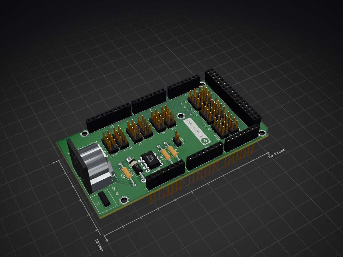
Pluralsight Floppy is an open-source printed circuit board by jzkmath, from the jzkmath/Arduino-MIDI-Floppy-Drive-Instrument repository on GitHub, published under the GPL-3.0 licence. It is a 2-layer board of 101.6 × 53.3 mm with 34 parts on 96 nets, routed with 425 tracks and 0 vias.
Its parts include 28 connectors, 3 resistors, 1 IC and 1 diode. It belongs with the audio and music and robots and motor control boards of this library.
This is the design files for an Arduino Floppy-Drive controller that is MIDI Controlled. It is a combination of the MIDI Stepper Synth V1 and Moppy Software.
The core method for controlling the floppy drives is the use of a non-blocking delay. If you want to make a stepper motor play at a certain frequency, simply pulse the pin at that specified frequency. In this case however, the position of the drive head is important, so we simply need to track the position and reverse direction when that point is reached.

Refer to the schematic for pinouts. The header pins connect to the IDE connector of the floppy drive and maintain the ground reference.
Look at this pinout:

We need to connect "drive select" together (Pins 11 and 12) to enable the drive and then connect the Step and Direction to the Shield.
12 - Drive Select (Enable)
11 - Drive Select Ground
18 - Direction
17 - Direction Ground
20 - Step
19 - Step Ground
There is a two pin header (J14) that is the programming jumper. The jumper should be installed here and removed when the Arduino is being programmed. This is because the MIDI Rx line is also use to program the Arduino when its being flashed.
| Qty | Value | Footprint | References |
|---|---|---|---|
| 6 | CONN_01X01 | Socket_Arduino_Mega:Arduino_1pin | P8, P9, P10, P11, P12, P13 |
| 2 | 220 | Resistors_THT:R_Axial_DIN0207_L6.3mm_D2.5mm_P15.24mm_Horizontal | R1, R3 |
| 2 | Analog | Socket_Arduino_Mega:Socket_Strip_Arduino_1x08 | P3, P4 |
| 1 | 1N914 | Diode_THT:D_DO-15_P15.24mm_Horizontal | D1 |
| 1 | 4.7k | Resistors_THT:R_Axial_DIN0207_L6.3mm_D2.5mm_P15.24mm_Horizontal | R2 |
| 1 | 6N138 | Package_DIP:DIP-8_W7.62mm_LongPads | U1 |
| 1 | Communication | Socket_Arduino_Mega:Socket_Strip_Arduino_1x08 | P7 |
| 1 | DIR1 | Pluralsight:PinHeader_2x04_P2.54mm_Vertical_zigzag | J8 |
| 1 | DIR2 | Pluralsight:PinHeader_2x04_P2.54mm_Vertical_zigzag | J9 |
| 1 | DIR3 | Pluralsight:PinHeader_2x04_P2.54mm_Vertical_zigzag | J10 |
| 1 | DIR4 | Pluralsight:PinHeader_2x04_P2.54mm_Vertical_zigzag | J11 |
| 1 | DIR5 | Pluralsight:PinHeader_2x04_P2.54mm_Vertical_zigzag | J12 |
| 1 | DIR6 | Pluralsight:PinHeader_2x04_P2.54mm_Vertical_zigzag | J13 |
| 1 | Digital | Socket_Arduino_Mega:Socket_Strip_Arduino_2x18 | P1 |
| 1 | LOGO | Pluralsight:Pluralsight Logo_Small | G*** |
| 1 | MIDI DIN | Connectors:SDS-50J | J1 |
| 1 | PWM | Socket_Arduino_Mega:Socket_Strip_Arduino_1x08 | P6 |
| 1 | PWM | Socket_Arduino_Mega:Socket_Strip_Arduino_1x10 | P5 |
| 1 | Power | Socket_Arduino_Mega:Socket_Strip_Arduino_1x08 | P2 |
| 1 | Power | Pluralsight:2_Pos_Screw_Term | J15 |
| 1 | Prog Jumper | Connector_PinHeader_2.54mm:PinHeader_1x02_P2.54mm_Vertical | J14 |
| 1 | STEP1 | Pluralsight:PinHeader_2x04_P2.54mm_Vertical_zigzag | J2 |
| 1 | STEP2 | Pluralsight:PinHeader_2x04_P2.54mm_Vertical_zigzag | J3 |
| 1 | STEP3 | Pluralsight:PinHeader_2x04_P2.54mm_Vertical_zigzag | J4 |
| 1 | STEP4 | Pluralsight:PinHeader_2x04_P2.54mm_Vertical_zigzag | J5 |
| 1 | STEP5 | Pluralsight:PinHeader_2x04_P2.54mm_Vertical_zigzag | J6 |
| 1 | STEP6 | Pluralsight:PinHeader_2x04_P2.54mm_Vertical_zigzag | J7 |

FrameworkComputer/ExpansionCards
Reference designs and documentation to create Expansion Cards for the Framework Laptop

mntmn/amiga2000-gfxcard
MNT VA2000, an Open Source Amiga 2/3/4000 Graphics Card (Zorro II/III), written in Verilog

hackclub/OnBoard
💡 Join 1,000 teenagers and make your first PCB with a $100 grant!


strangeparts/niubi-headphones
Flexible circuit board design for adding a headphone jack to an iPhone 7


baldengineer/bit-preserve
Project for capturing vintage, classic, aka old computer schematics in KiCad.
It measures 101.6 × 53.3 mm and has 2 copper layers, 1.6 mm thick.
34 parts. The full list of its parts is on this page, with links to each part's symbol and footprint where PCBKit's library has them.
From the jzkmath/Arduino-MIDI-Floppy-Drive-Instrument repository on GitHub, at the commit this page was made from: the board is KiCAD/Pluralsight_Floppy/Pluralsight_Floppy.kicad_pcb. PCBKit opens the board in the browser, with nothing to install.
Its repository publishes it under the GPL-3.0 licence: you may reuse it on that licence's terms (keep the author's notice, and for a copyleft licence share your changes alike).