4 layers90 × 87.6 mm

 justsem/badPico2
An RP2040 mini-sized BadUSB clone
BadPico is an open-source printed circuit board by justsem, from the justsem/badPico repository on GitHub, published under the CC-BY-SA-4.0 licence. It is a 2-layer board of 19 × 39 mm with 48 parts on 60 nets, routed with 238 tracks and 29 vias.
It is built around the RP2040, W25Q128JVSIQ and SPX3819M5-L-3-3, with the 0805L050WR and SI2319CDS among its other parts. Its parts include 16 capacitors, 9 resistors, 3 ICs, 3 diodes and 3 switches. It belongs with the RP2040 boards of this library.


An RP2040 mini-sized BadUSB clone
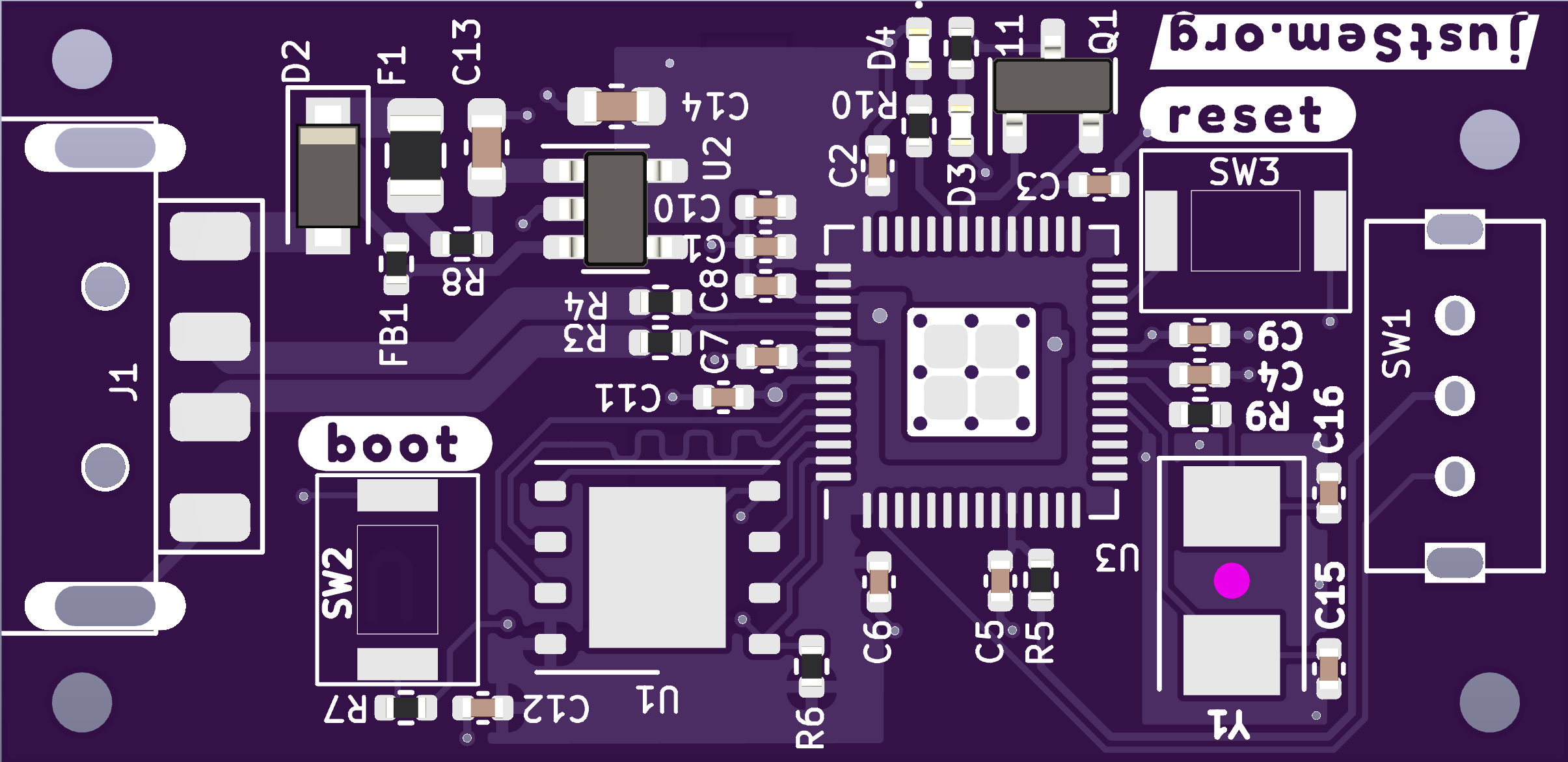 Size: 19x39mm
This tiny (19x34mm) device is just a common "Rubber Ducky" clone.
Without software this is just an RP2040-on-a-stick ;)
A good starting point for this board is the BadPico Repository by @EvgeniGenchev.
The board in general works identical to a Raspberry Pi Pico and can be programmed as such. However, due to the intended use-case the I/O pins are not available for usage with the exception of those listed below.
| Designator | GPIO | Type | Description |
|---|---|---|---|
| D4 | 25 | LED | Status LED |
| D3 | 24 | LED | User-programmable LED |
| SW1 | 0 | Switch | User-programmable switch. I use it as an 'arming' switch |
| Name | Designator | Footprint | Manufacturer | Man. Part No. |
|---|---|---|---|---|
| 27pF | C15,C16 | C0402 | FH | 0402CG270J500NT |
| 100nF | C1-C9,C12 | C0402 | Yaego | CC0402KRX7R7BB104 |
| 1uF | C10,C11 | C0402 | Samsung | CL05A105KQ5NNNC |
| 10uF | C13,C14 | C0603 | Samsung | CL10A106MP8NNNC |
| Y | Y1 | 5032 | Abracon | ABMM2-12.000MHZ-E2-T |
| 24.7R | R3,R4 | R0402 | FH | RC-02W27R4FT |
| 330R | R5 | R0402 | FOJAN | FRC1206J331 |
| 1k | R7,R9,R10,R11 | R0402 | Walsin | MR04X102 |
| 100k | R8 | R0402 | FH | RS-03K104JT |
| Flash | U1 | WSON-8 | Winbond Elec | W25Q128JVPIQ |
| LDO | U2 | TSOT-23-5 | Maxlinear | SPX3819M5-L-3-3 |
| RP2040 | U3 | QFN-56 | Raspberry Pi | RP2040 |
| FET | Q1 | SOT-24 | Vishay | Si2319CDS |
| Diode | D2 | SOD_123F | Shandong | 1N4002W |
| LEDs | D3,D4 | D0402 | Everlight | 17-21/BHC-XL2M2TY/3T |
| Fuse | F1 | F0805 | LittelFuse | 0805L050WR |
| Bead | FB1 | F0402 | Chillsin | BBSY00100505101Y00 |
| USB | J1 | Custom | XKB Connectivity | U217-041N-4BV81 |
| SWT | SW2,SW3 | Custom | ALPS | SKRKAEE020 |
| SWF | SW1 | Custom | Shou Han | SK12D07VG4 |
| Qty | Value | Footprint | References |
|---|---|---|---|
| 10 | 100nF | Capacitor_SMD:C_0402_1005Metric | C1, C2, C3, C4, C5, C6, C7, C8, C9, C12 |
| 3 | 330 | Resistor_SMD:R_0402_1005Metric | R5, R10, R11 |
| 3 | TestPoint | TestPoint:TestPoint_Pad_2.0x2.0mm | TP3, TP4, TP5 |
| 2 | 10uF | Capacitor_SMD:C_0603_1608Metric | C13, C14 |
| 2 | 1k | Resistor_SMD:R_0402_1005Metric | R7, R9 |
| 2 | 1uF | Capacitor_SMD:C_0402_1005Metric | C10, C11 |
| 2 | 27.4 | Resistor_SMD:R_0402_1005Metric | R3, R4 |
| 2 | 32pF | Capacitor_SMD:C_0402_1005Metric | C15, C16 |
| 2 | BOOT | ALPS:SW_SPST_ALPS_SKRKAEE020 | SW2, SW3 |
| 2 | LED | LED_SMD:LED_0402_1005Metric | D3, D4 |
| 1 | Graphics:jsorg-fs | ||
| 1 | Graphics:reset-lc-ca | ||
| 1 | Graphics:boot-lc-ca | ||
| 1 | Graphics:r1_0-ca | ||
| 1 | Graphics:rev-cc-ha | ||
| 1 | Graphics:date-cc-ha | ||
| 1 | 0402 | Resistor_SMD:R_0402_1005Metric | FB1 |
| 1 | 0805L050WR | Fuse:Fuse_0805_2012Metric | F1 |
| 1 | 100k | Resistor_SMD:R_0402_1005Metric | R8 |
| 1 | 1N4002 | Diode_SMD:D_SOD-123F | D2 |
| 1 | ARM | Button_Switch_THT:SW_DPDT_SK12D07VG4 | SW1 |
| 1 | Crystal | Crystal:Crystal_SMD_5032-2Pin_5.0x3.2mm | Y1 |
| 1 | DNF | Resistor_SMD:R_0402_1005Metric | R6 |
| 1 | RP2040 | RPi:RP2040-QFN-56 | U3 |
| 1 | SPX3819M5-L-3-3 | Package_TO_SOT_SMD:SOT-23-5 | U2 |
| 1 | Si2319CDS | Package_TO_SOT_SMD:SOT-23 | Q1 |
| 1 | USB_A | Connector_USB:Male_Type-A-XKB-U217-041N-4BV81 | J1 |
| 1 | W25Q128JVS | Package_SON:WSON-8-1EP_6x5mm_P1.27mm_EP3.4x4mm | U1 |
It measures 19 × 39 mm and has 2 copper layers, 1.06 mm thick.
48 parts, built around the RP2040, W25Q128JVSIQ, SPX3819M5-L-3-3 and 0805L050WR. The full list of its parts is on this page, with links to each part's symbol and footprint where PCBKit's library has them.
From the justsem/badPico repository on GitHub, at the commit this page was made from: the board is Board Files/BadPico.kicad_pcb and its schematic Board Files/BadPico.kicad_sch. PCBKit opens the board in the browser, with nothing to install.
Its repository publishes it under the CC-BY-SA-4.0 licence: you may reuse it on that licence's terms (keep the author's notice, and for a copyleft licence share your changes alike).

Kirg5/2040Inverter
RP2040 Based BLDC Inverter for sensored motors, capable of putting out 50a 100v

MasaoC/GPS-TFT-Map_PONS
鳥人間コンテストに特化したGNSS誘導システム。人力飛行機のパイロットが使いやすいことを目標にした航法装置です。ハードとソフトをオープンソースで開発しています。

RetroScaler/RP2040-PICO-BOOT
Raspberry PI RP2040 PICOBOOT for the Game cube console

Auroxin/N64xCart-Dumper
an open hardware / firmware project for dumping Nintendo 64 cartridges as a USB mass storage device


TrojanPinata/Model-B
A 75% keyboard based on the RP2040 - with hotswappable switches, OLED display and rotary encoder

pustowhite/rp2040-logic-analyzer
An 8-channel RP2040 logic analyzer PCB designed in KiCad, with USB-C and selectable 1.8 V / 3.3 V input logic modes.