
2 layers68.8 × 53.6 mm
ZArduino
zmaker/arduino_cookbook
gli sketch del nuovo progetto Arduino Cookbook e dei video di YouTube
46 parts269

 justfulofluck/Standalone_ATmega382
The Standalone ATmega 328 Board is a versatile hardware module designed for embedded systems development and IOT rapid prototyping.
Standalone arduino is an open-source printed circuit board by justfulofluck, from the justfulofluck/Standalone_ATmega382 repository on GitHub. It is a 2-layer board of 33 × 58.4 mm with 9 parts on 26 nets, routed with 84 tracks and 0 vias.
It is built around the ATMEGA328P-PU. Its parts include 2 capacitors, 2 connectors, 1 resistor, 1 IC and 1 switch. It belongs with the AVR (ATmega, ATtiny) boards of this library.
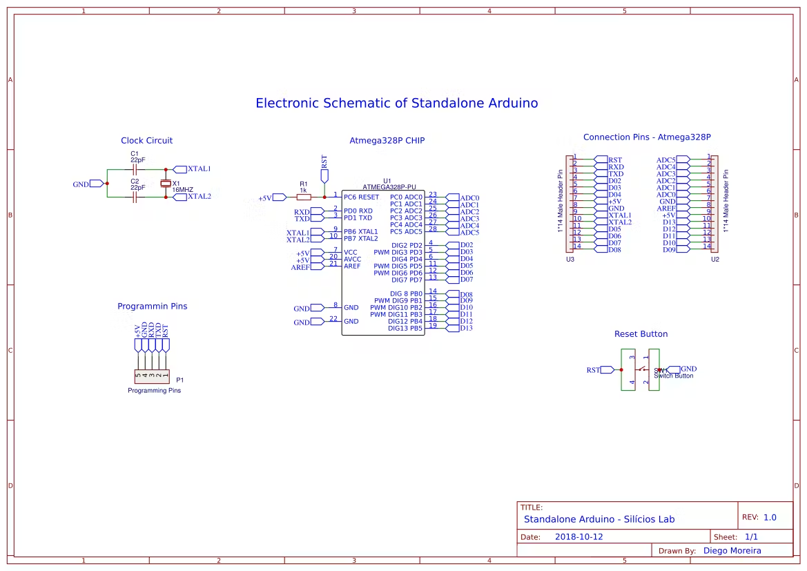
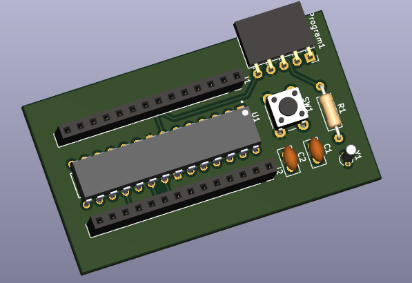
A minimal, cost-effective Arduino-compatible development board based on the ATmega328P microcontroller.
This project provides a complete KiCad design for a standalone ATmega328P-based development board. It replicates the core functionality of an Arduino Uno while eliminating unnecessary components (such as the USB-to-serial converter), making it ideal for:
Once programmed via an external ISP programmer or Arduino-as-ISP, this board operates independently to run your Arduino sketches.
| Component | Value/Part Number | Quantity | Notes |
|---|---|---|---|
| U1 | ATmega328P-PU | 1 | DIP-28 package |
| Y1 | 16MHz Crystal Oscillator | 1 | External clock source |
| C1, C2 | 22pF Ceramic Capacitor | 2 | Crystal load capacitors |
| C3, C4 | 100nF Ceramic Capacitor | 2 | Power decoupling |
| R1 | 10kΩ Resistor | 1 | RESET pull-up |
| SW1 | Tactile Push Button | 1 | Reset button |
| HDR1 | 2x3 Pin Header | 1 | ISP programming header |
| HDR2, HDR3 | Female Pin Headers | 2 | I/O breakout (Arduino Uno footprint) |
| J1 | DC Power Jack / Pin Header | 1 | 5V power input |
Note: Adjust capacitor values if using a different crystal frequency.
Clone or Download this repository:
git clone <repository-url>
cd <project-directory>
Open the Project in KiCad:
standalone_arduino.kicad_proReview Schematic & PCB:
standalone_arduino.kicad_sch to view/edit the schematicstandalone_arduino.kicad_pcb to view/edit the PCB layoutGenerate Manufacturing Files (if modifications are made):
Since this board lacks a built-in USB-to-serial converter, you have two options for uploading code:
💡 Tip: After initial programming via ISP, you can use a USB-to-TTL adapter (FTDI/CH340) connected to TX/RX pins for serial communication and bootloader-based uploads if a bootloader is installed.
├── README.md                     # This documentation file
├── standalone_arduino.kicad_pro  # KiCad project file
├── standalone_arduino.kicad_sch  # Schematic design
├── standalone_arduino.kicad_pcb  # PCB layout (2-layer)
├── *.gbr                         # Gerber files for manufacturing
│   ├── standalone_arduino-F_Cu.gbr       # Front Copper
│   ├── standalone_arduino-B_Cu.gbr       # Back Copper
│   ├── standalone_arduino-F_Silkscreen.gbr
│   ├── standalone_arduino-B_Silkscreen.gbr
│   ├── standalone_arduino-F_Mask.gbr     # Front Solder Mask
│   ├── standalone_arduino-B_Mask.gbr     # Back Solder Mask
│   ├── standalone_arduino-F_Paste.gbr    # Front Solder Paste
│   ├── standalone_arduino-B_Paste.gbr    # Back Solder Paste
│   └── standalone_arduino-Edge_Cuts.gbr  # Board Outline
├── schematic_arduino-standal.avif # Schematic diagram image
├── 3D_bord_view.png              # 3D render of the PCB
├── Two_layer_scyamtics.png       # Layer visualization
└── standalone_arduino-backups/ # Automatic backup archivesThe included Gerber files are ready to send to any PCB fabrication service (e.g., JLCPCB, PCBWay, OSH Park).
Simply upload the .gbr files (compressed into a .zip folder) to your manufacturer's website and select the above specifications.
| Issue | Possible Cause | Solution |
|---|---|---|
| Board not powering on | Incorrect power polarity | Verify 5V and GND connections |
| Cannot upload code | Wrong programmer selected | Ensure correct programmer is chosen in Arduino IDE |
| Microcontroller not responding | Missing/bad crystal or caps | Check oscillator circuit and solder joints |
| Reset not working | Faulty button or pull-up resistor | Test continuity of reset circuit |
Contributions are welcome! Feel free to:
This project is open-source. Please refer to the LICENSE file (if included) or contact the author for usage rights.
For questions, suggestions, or collaboration opportunities, please open an issue in this repository or contact the project maintainer directly.
Happy Building! 🚀
Designed with KiCad | Made for Makers
| Qty | Value | Footprint | References |
|---|---|---|---|
| 2 | 22 PF | Capacitor_THT:C_Disc_D5.0mm_W2.5mm_P2.50mm | C1, C2 |
| 2 | PINHD_1x14_Female | Connector_PinSocket_2.54mm:PinSocket_1x14_P2.54mm_Vertical | J1, J2 |
| 1 | 10K | Resistor_THT:R_Axial_DIN0207_L6.3mm_D2.5mm_P10.16mm_Horizontal | R1 |
| 1 | ATMEGA328P-PU | ATMEGA328P-PU:DIP794W46P254L2967H457Q28B | U1 |
| 1 | Crystal | Crystal:Crystal_C26-LF_D2.1mm_L6.5mm_Vertical | Y1 |
| 1 | PINHD_1x5_Female | Connector_PinSocket_2.54mm:PinSocket_1x05_P2.54mm_Horizontal | Program1 |
| 1 | Push_Button | Button_Switch_THT:SW_PUSH_6mm | SW1 |
zmaker/arduino_cookbook
gli sketch del nuovo progetto Arduino Cookbook e dei video di YouTube

coseyfannitutti/discipad
17-key numpad assembled with only through hole components, including usb type-c

matthewcieplak/super-sixteen
Code and schematics for the Super Sixteen Eurorack sequencer

coseyfannitutti/romeo
Staggered 40% keyboard pcb that can be assembled with only through hole components, including USB Type-C

mattybrad/drumkid
Version 4 was the first successful working design, with full code, schematics, Gerbers, etc available on GitHub.


leomil72/LM80C
A Z80-based homebrew computer withTMS9918, AY-3-8910, Z80 CTC, Z80 PIO, and Z80 SIO

It measures 33 × 58.4 mm and has 2 copper layers, 1.6 mm thick.
9 parts, built around the ATMEGA328P-PU. The full list of its parts is on this page, with links to each part's symbol and footprint where PCBKit's library has them.
From the justfulofluck/Standalone_ATmega382 repository on GitHub, at the commit this page was made from: the board is standalone_arduino.kicad_pcb and its schematic standalone_arduino.kicad_sch. PCBKit opens the board in the browser, with nothing to install.
Its repository states no licence, so its author keeps all rights: ask justfulofluck before reusing the design.