
4 layers99 × 53.3 mm
PSLab
fossasia/pslab-hardware
PSLab Hardware Design and Schematics https://pslab.io
199 parts1.7kApache-2.0

 juro97/iot-edu-shield
This repository contains the KiCad hardware files and some starter code for testing the IoT-Edu-Shield.
Iot edu shield is an open-source printed circuit board by juro97, from the juro97/iot-edu-shield repository on GitHub. It is a 2-layer board of 135.5 × 73.5 mm with 24 parts on 40 nets, routed with 147 tracks and 52 vias.
It is built around the WS2812B. Its parts include 9 resistors, 4 diodes, 4 connectors, 3 capacitors and 2 switches. It belongs with the home automation and IoT boards of this library.
A KiCad-designed shield for the LilyGO T3-S3 (LoRa32 / ESP32-S3) that bundles a handful of classic sensors, actuators and I/O onto one board for teaching IoT, wireless communication and embedded C++ concepts. This repository contains the hardware design files and starter firmware for testing the shield.
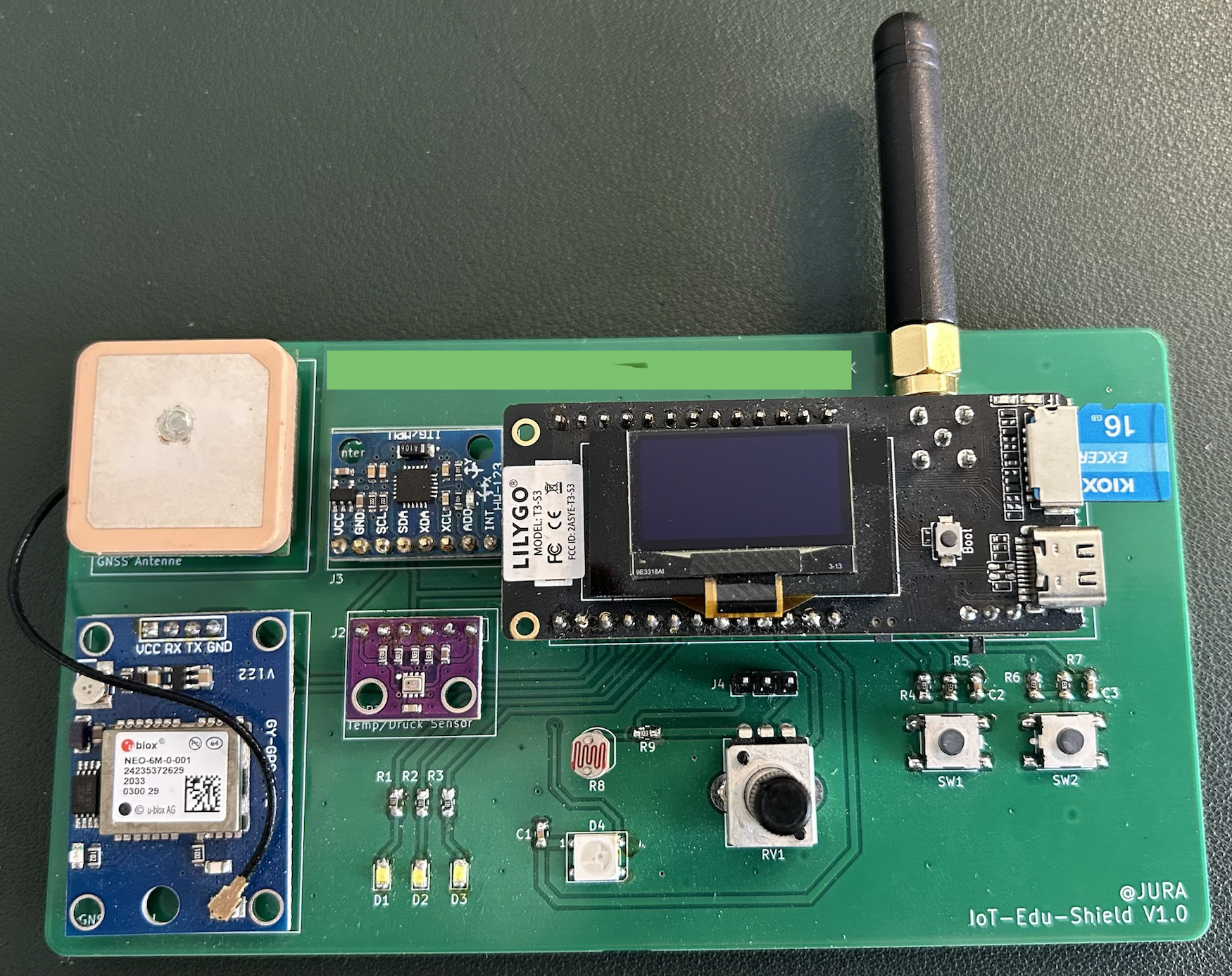
Assembled IoT-Edu-Shield V1.0 with LilyGO T3-S3, GPS module + GNSS antenna, MPU6050 IMU, BMP/BME temperature-pressure sensor, RGB LEDs, buttons, potentiometer and LDR.
iot-edu-shield/
├── kicad-files/     KiCad 9 project (schematic, PCB, backups)
├── demo-software/   Starter / example firmware (PlatformIO, C++)
├── img/             Photos and renders
└── README.mdThe shield is built around the LilyGO T3-S3, an ESP32-S3 module that combines three radios on one board:
It also carries a 0.96" SSD1306 OLED display, a microSD card slot, USB-C (incl. LiPo battery charging), and BOOT/reset buttons — all visible on the module plugged into the shield.
| Ref | Module | Interface | MCU pin(s) | Notes |
|---|---|---|---|---|
| D4 | WS2812B addressable RGB LED | 1-wire data | GPIO38 | Single NeoPixel-style LED |
| D1–D3 | Discrete Red/Green/Blue LEDs | GPIO (PWM-capable) | GPIO39 / GPIO40 / GPIO41 | 3 independent single-color LEDs via current-limiting resistors R1–R3 |
| SW1, SW2 | Push buttons | Digital in, debounced (RC) | GPIO48 / GPIO47 | Pulled up to 3V3, active low |
| R8 (LDR) + RV1 (potentiometer) | Light sensor / manual analog input | Analog (shared) | GPIO8 | Selectable via jumper header J4: bridge to use either the onboard LDR or the potentiometer as the analog source |
| J1 | GPS/GNSS header (populated: u-blox NEO-6M + GNSS patch antenna) | UART | GPIO43 (RX) / GPIO44 (TX) | 4-pin: 3V3, RX, TX, GND |
| J2 | I²C sensor header (populated: BMP/BME-style temperature & pressure sensor) | I²C | GPIO46 (SDA) / GPIO42 (SCL) | 6-pin, 2 spare pins |
| J3 | IMU header (populated: MPU6050 6-axis accelerometer/gyroscope) | I²C + interrupt | GPIO46 (SDA) / GPIO42 (SCL) / GPIO45 (INT) | 8-pin, shares the I²C bus with J2, 3 spare pins |
Combining LoRaWAN + Wi-Fi + BLE with GPS, an IMU and an environmental sensor on one educational board opens up a lot of classic IoT project patterns:
kicad-files/IoT-Edu-Shield.kicad_pro in KiCad 9.demo-software/ (PlatformIO project, C++/Arduino framework).| Qty | Value | Footprint | References |
|---|---|---|---|
| 8 | R | Resistor_SMD:R_0805_2012Metric_Pad1.20x1.40mm_HandSolder | R1, R2, R3, R4, R5, R6, R7, R9 |
| 3 | C | Capacitor_SMD:C_0805_2012Metric_Pad1.18x1.45mm_HandSolder | C1, C2, C3 |
| 3 | LED | LED_SMD:LED_0805_2012Metric_Pad1.15x1.40mm_HandSolder | D1, D2, D3 |
| 2 | SW_Push | Button_Switch_SMD:SW_SPST_PTS645 | SW1, SW2 |
| 1 | Conn_01x03_Pin | Connector_PinHeader_2.54mm:PinHeader_1x03_P2.54mm_Vertical | J4 |
| 1 | Conn_01x04_Socket | Connector_PinSocket_2.54mm:PinSocket_1x04_P2.54mm_Vertical | J1 |
| 1 | Conn_01x06_Socket | Connector_PinSocket_2.54mm:PinSocket_1x06_P2.54mm_Vertical | J2 |
| 1 | Conn_01x08_Socket | Connector_PinSocket_2.54mm:PinSocket_1x08_P2.54mm_Vertical | J3 |
| 1 | LDR07 | OptoDevice:R_LDR_5.1x4.3mm_P3.4mm_Vertical | R8 |
| 1 | LILYGO T3S3 V1.2 | PCM_Espressif:ESP32-S3-DevKitC | U1 |
| 1 | R_Potentiometer_MountingPin | Potentiometer_THT:Potentiometer_Bourns_PTV09A-1_Single_Vertical | RV1 |
| 1 | WS2812B | LED_SMD:LED_WS2812B_PLCC4_5.0x5.0mm_P3.2mm | D4 |
It measures 135.5 × 73.5 mm and has 2 copper layers, 1.6 mm thick.
24 parts, built around the WS2812B. The full list of its parts is on this page, with links to each part's symbol and footprint where PCBKit's library has them.
From the juro97/iot-edu-shield repository on GitHub, at the commit this page was made from: the board is kicad-files/IoT-Edu-Shield.kicad_pcb and its schematic kicad-files/IoT-Edu-Shield.kicad_sch. PCBKit opens the board in the browser, with nothing to install.
Its repository states no licence, so its author keeps all rights: ask juro97 before reusing the design.
fossasia/pslab-hardware
PSLab Hardware Design and Schematics https://pslab.io

FrameworkComputer/ExpansionCards
Reference designs and documentation to create Expansion Cards for the Framework Laptop


PrintersForAnts/Micron
If you want to purchase full kits there are 3 available (Kits are slowly updating to R1 hardware just make sure to double check the included hardware in your kit and if you have any questions reach out in the discord)


