
2 layers100 × 100 mm
Langpie
langpie/langpie
An Opensource Raspberry Pi Based Smart Car Project (ORPSC Project) - 树莓派开源智能车项目
80 parts48

 jtljac/printer-pi-gpio
A quick breakout board for the Raspberry pi (in my case, the pi zero 2), for breaking out some key interfaces into convenient sockets
Pi gpio is an open-source printed circuit board by jtljac, from the jtljac/printer-pi-gpio repository on GitHub. It is a 2-layer board of 65.1 × 30.1 mm with 17 parts on 38 nets, routed with 109 tracks and 3 vias.
It is built around the B340A-13-F-MS. Its parts include 8 connectors, 5 diodes and 4 resistors. It belongs with the interfaces and adapters boards of this library.
A simple break-out board for a Raspberry Pi that makes accessing some GPIO interfaces easier for klipper.
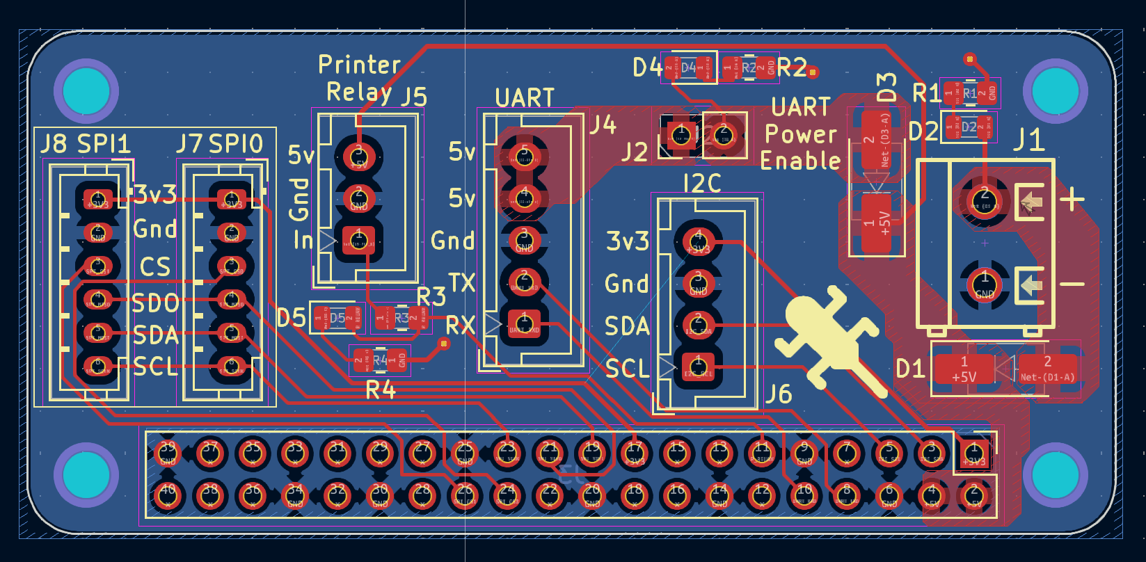
5V Power in via screw terminal for powering Pi.
UART Bus for connecting klipper directly to a control board via serial.
The UART bus also has 2 pins for 5V, which depending on your control board can power the Pi (In my case, the SKR-Pico supports this). This can be enabled using the UART Power Enable jumper.
Reverse current protection on both power inputs, also doubling as Power Or-ing, allowing both power inputs to be powered simultaniously safely.
LED indicators on each power input to indicate when each one is powered.
SPI bus split into 2 connectors with different CS pins (spi0: GPIO8, spi1: GPIO7), for screens and ADXLs.
I2C bus for miscellaneous purposes.
A header for connecting to a Relay Module to toggle power to the actual printer, uses GPIO17.
Also features an LED to indicate when the relay is toggled.
| Qty | Value | Footprint | References |
|---|---|---|---|
| 2 | 150R | Resistor_SMD:R_0805_2012Metric_Pad1.20x1.40mm_HandSolder | R1, R2 |
| 2 | B340A-13-F | Diode_SMD:D_SMA_Handsoldering | D1, D3 |
| 2 | Red | LED_SMD:LED_0805_2012Metric | D2, D4 |
| 1 | 1K | Resistor_SMD:R_0805_2012Metric_Pad1.20x1.40mm_HandSolder | R3 |
| 1 | 22R | Resistor_SMD:R_0805_2012Metric_Pad1.20x1.40mm_HandSolder | R4 |
| 1 | Green | LED_SMD:LED_0805_2012Metric | D5 |
| 1 | Raspberry_Pi_2_3 | jacob-libs:RaspberryPi_Zero_BoardLayout | J3 |
| 1 | SPI0 | Connector_JST:JST_PH_B6B-PH-K_1x06_P2.00mm_Vertical | J7 |
| 1 | SPI1 | Connector_JST:JST_PH_B6B-PH-K_1x06_P2.00mm_Vertical | J8 |
| 1 | UART | Connector_JST:JST_XH_B5B-XH-A_1x05_P2.50mm_Vertical | J4 |
| 1 | i2c | Connector_JST:JST_XH_B4B-XH-A_1x04_P2.50mm_Vertical | J6 |
| 1 | powerIn | jacob-libs:TerminalBlock_MAX_MX127-5.0-02P_1x02_P5.00mm | J1 |
| 1 | printerRelay | Connector_JST:JST_XH_B3B-XH-A_1x03_P2.50mm_Vertical | J5 |
| 1 | uartPower | Connector_PinHeader_2.54mm:PinHeader_1x02_P2.54mm_Vertical | J2 |
It measures 65.1 × 30.1 mm and has 2 copper layers, 1.6 mm thick.
17 parts, built around the B340A-13-F-MS. The full list of its parts is on this page, with links to each part's symbol and footprint where PCBKit's library has them.
From the jtljac/printer-pi-gpio repository on GitHub, at the commit this page was made from: the board is pi-gpio.kicad_pcb and its schematic pi-gpio.kicad_sch. PCBKit opens the board in the browser, with nothing to install.
Its repository states no licence, so its author keeps all rights: ask jtljac before reusing the design.
langpie/langpie
An Opensource Raspberry Pi Based Smart Car Project (ORPSC Project) - 树莓派开源智能车项目

EwoudVV/ducktop2
An open-source 16-inch laptop designed from scratch.

NVIDIA-AI-IOT/jetbot_mini
While developing the schematic and layout designs, I used some footprints from SnapEDA; in order to avoid dealing with licensing issues, I will not redistribute those files on this Github and instead link to where you…

NicholasKorth/BedCooler
A dual-zone heating and cooling controller for a bed: a 6-layer KiCad board with an STM32G474 real-time controller and a Raspberry Pi Compute Module 5 host.


nuerolynx/embedded-systems-lab
Arduino UNO R4 WiFi and ESP32 prototypes for access control, automation, displays, monitoring, and Bluetooth audio.

misko/prompt2device
The separate vNext PCB skill and orchestrator package is available alongside the reference workflow below; existing projects keep their accepted toolchain until an explicit migration.
