
2 layers53.8 × 38.1 mm

 jscrane/DevBoards
Development boards for hardware used in Arduino projects
T84opti is an open-source printed circuit board by jscrane, from the jscrane/DevBoards repository on GitHub, published under the MIT licence. It is a 2-layer board of 18.3 × 52.1 mm with 10 parts on 16 nets, routed with 79 tracks and 0 vias.
It is built around the ATTINY84A-PU. Its parts include 3 connectors, 2 capacitors, 2 resistors, 1 IC and 1 diode. It belongs with the interfaces and adapters boards and the AVR (ATmega, ATtiny) boards of this library.
View this project on CADLAB.io.
Development and breakout boards for use in Arduino projects, with Gerbers.
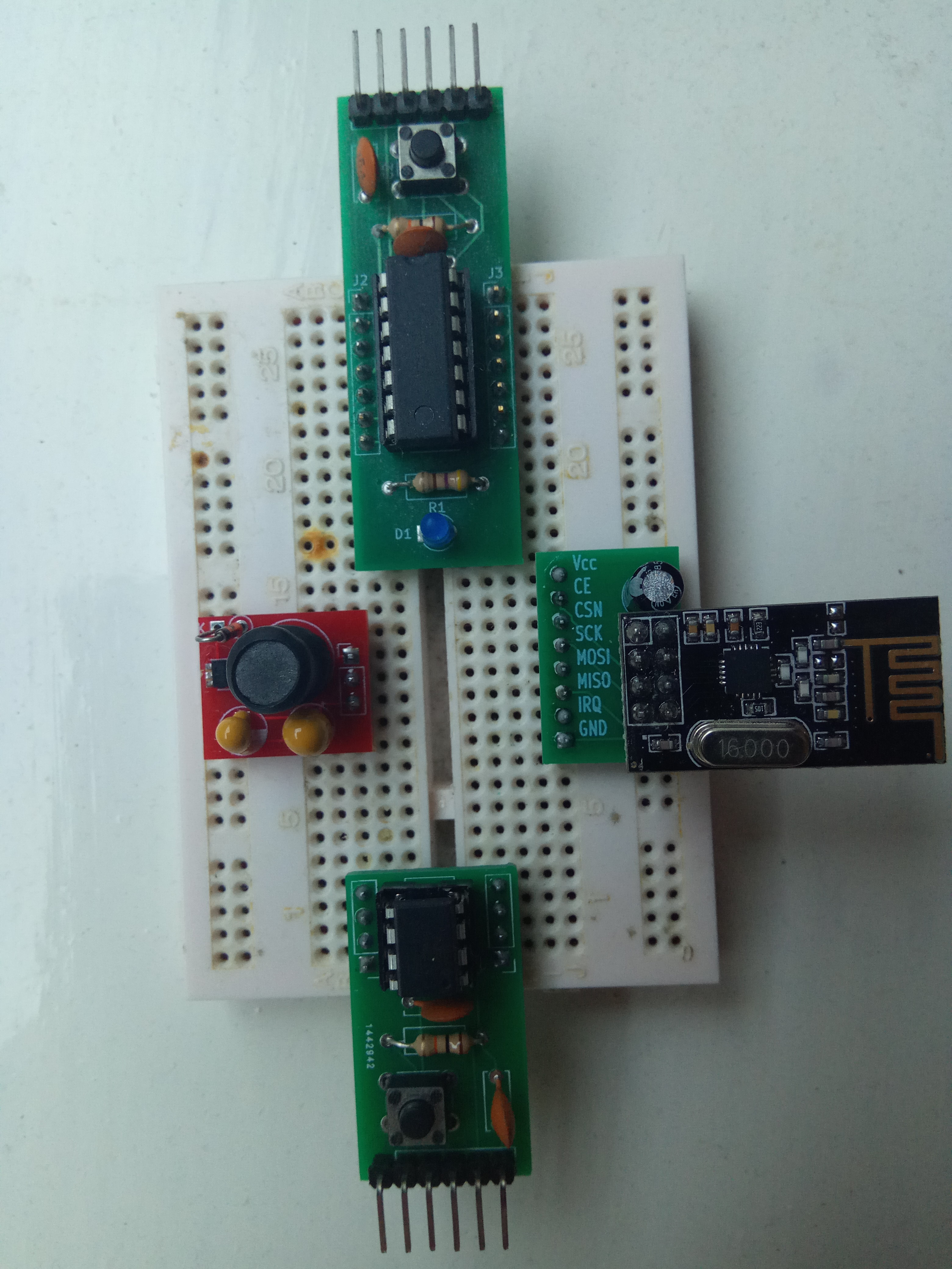
An ATtiny84 development board with FTDI interface. Works very well with Optiboot, in particular with the ATTinyCore. (Top, in picture.)
Same as t84opti, except with ATtiny85, and no LED_BUILTIN. (Bottom, in picture.)
A breadboard adapter for the nrf24l01 short-range wireless module. (Right, in picture.)
A breadboard adapter for the ncp1402 step-up switching regulator ("boost converter"). (Left, in picture.) Warning: SMD soldering required!
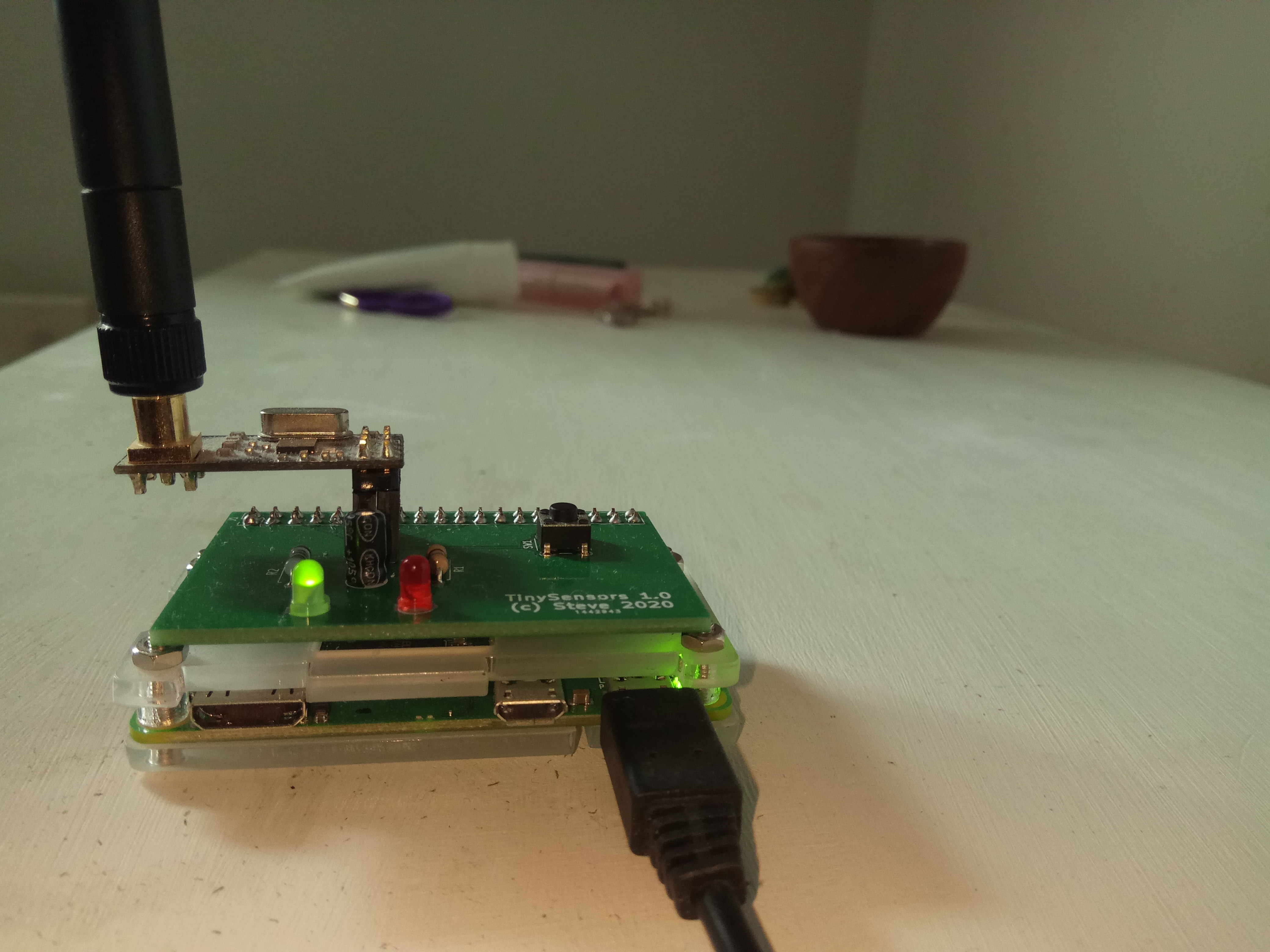
A Raspberry Pi "hat" containing an SPI-connected nrf24l01+ radio, two status LEDs and a shutdown button.
A shield for the popular Wemos D1 Mini ESP8266 board containing an SPI-connected nrf24l01+ radio.
| Qty | Value | Footprint | References |
|---|---|---|---|
| 2 | 100n | Capacitor_THT:C_Disc_D6.0mm_W2.5mm_P5.00mm | C1, C2 |
| 1 | 10k | Resistor_THT:R_Axial_DIN0207_L6.3mm_D2.5mm_P10.16mm_Horizontal | R2 |
| 1 | 470 | Resistor_THT:R_Axial_DIN0207_L6.3mm_D2.5mm_P10.16mm_Horizontal | R1 |
| 1 | ATtiny84A-PU | Package_DIP:DIP-14_W7.62mm | U1 |
| 1 | LED_BUILTIN | LED_THT:LED_D3.0mm | D1 |
| 1 | SW_Push | Button_Switch_THT:SW_PUSH_6mm_H7.3mm | SW1 |
| 1 | ftdi | Connector_PinHeader_2.54mm:PinHeader_1x06_P2.54mm_Vertical | J1 |
| 1 | left | Connector_PinHeader_2.54mm:PinHeader_1x07_P2.54mm_Vertical | J2 |
| 1 | right | Connector_PinHeader_2.54mm:PinHeader_1x07_P2.54mm_Vertical | J3 |
It measures 18.3 × 52.1 mm and has 2 copper layers, 1.6 mm thick.
10 parts, built around the ATTINY84A-PU. The full list of its parts is on this page, with links to each part's symbol and footprint where PCBKit's library has them.
From the jscrane/DevBoards repository on GitHub, at the commit this page was made from: the board is t84opti/t84opti.kicad_pcb. PCBKit opens the board in the browser, with nothing to install.
Its repository publishes it under the MIT licence: you may reuse it on that licence's terms (keep the author's notice, and for a copyleft licence share your changes alike).


jscrane/DevBoards
Development boards for hardware used in Arduino projects


copperheadhq/copperhead-quiet-orbit
USB-C four-light ambient lamp, 57 mm, ATtiny84A hardware PWM. Designed with copperhead. Never built: do not order expecting it to work.


arcadien/tinySensor
Firmware and generic board for low-power environment sensors


pddenhar/Volvo_240_Info_Display
OLED dashboard module for the Volvo 240 displaying battery voltage, speed, and RPM.

BryceVandegrift/hot-plate
A DIY PCB hot plate that uses through hole components

AhmedAtefNasr/PCB_Course-IMT_school
Here's the repo for Assignments & projects of PCB course from IMT school

Brawn1/ATTiny-Door-Sensor
Door Sensor Battery based with Attiny84 and HC-12 Sender