2 layers78.5 × 100 mm
DAQ Rev 2
ikmitche/OSHE-RecycleBot
The Home of the Open Source Hardware Enterprise's RecycleBot Project
43 parts

 jrlomas/vfd-rat-king
A VFD control board for RatRig's Rodent Board
Vfd rat king is an open-source printed circuit board by jrlomas, from the jrlomas/vfd-rat-king repository on GitHub. It is a 2-layer board of 40 × 45 mm with 13 parts on 25 nets, routed with 91 tracks and 2 vias.
It is built around the CD74HC4050EG4 and ILQ615-3. Its parts include 4 resistors, 2 ICs, 2 connectors and 1 capacitor. It belongs with the lEDs and displays boards of this library.

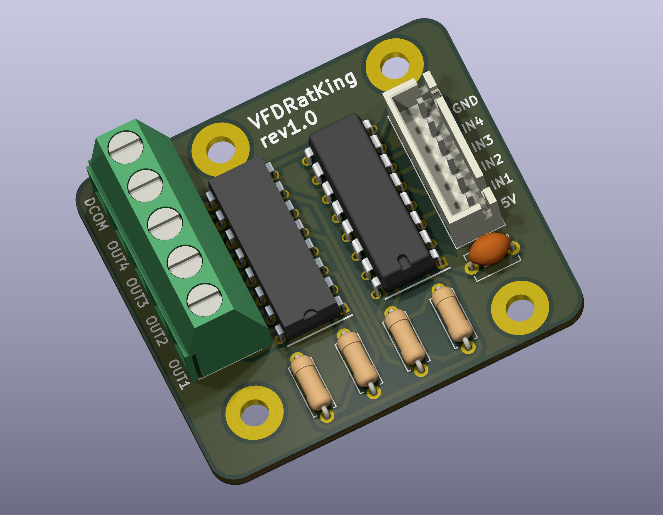
Welcome to the VFDRatKing project! This custom-designed board is your solution for safely controlling your CNC spindle via a VFD using the Rodent Board by RatRig. Why, you ask? Because the RS485 implementation in FluidNC is as dependable as a wet napkin in a rainstorm. Seriously, when the Rodent loses connection, the spindle doesn't stop. That's a bit "iffy," wouldn't you say?
But that's not all! If you were trying to use the built-in relay in your VFD to control air, mist, or a water pump while hardwiring DCOM to FOR (Forward), you're probably having a bad time. This board is here to save the day by properly isolating signals and giving you precise control without these headaches. Designed by knight_rad.iant on Discord, this project brings a practical solution to your CNC workflow.
The board operates as an intermediary between the Rodent MCU (3.3V logic) and your spindle's VFD. Here's how the magic happens:
Logic Signal Conditioning:
Optocoupler Isolation:
Signal Translation:
Connector Interface:
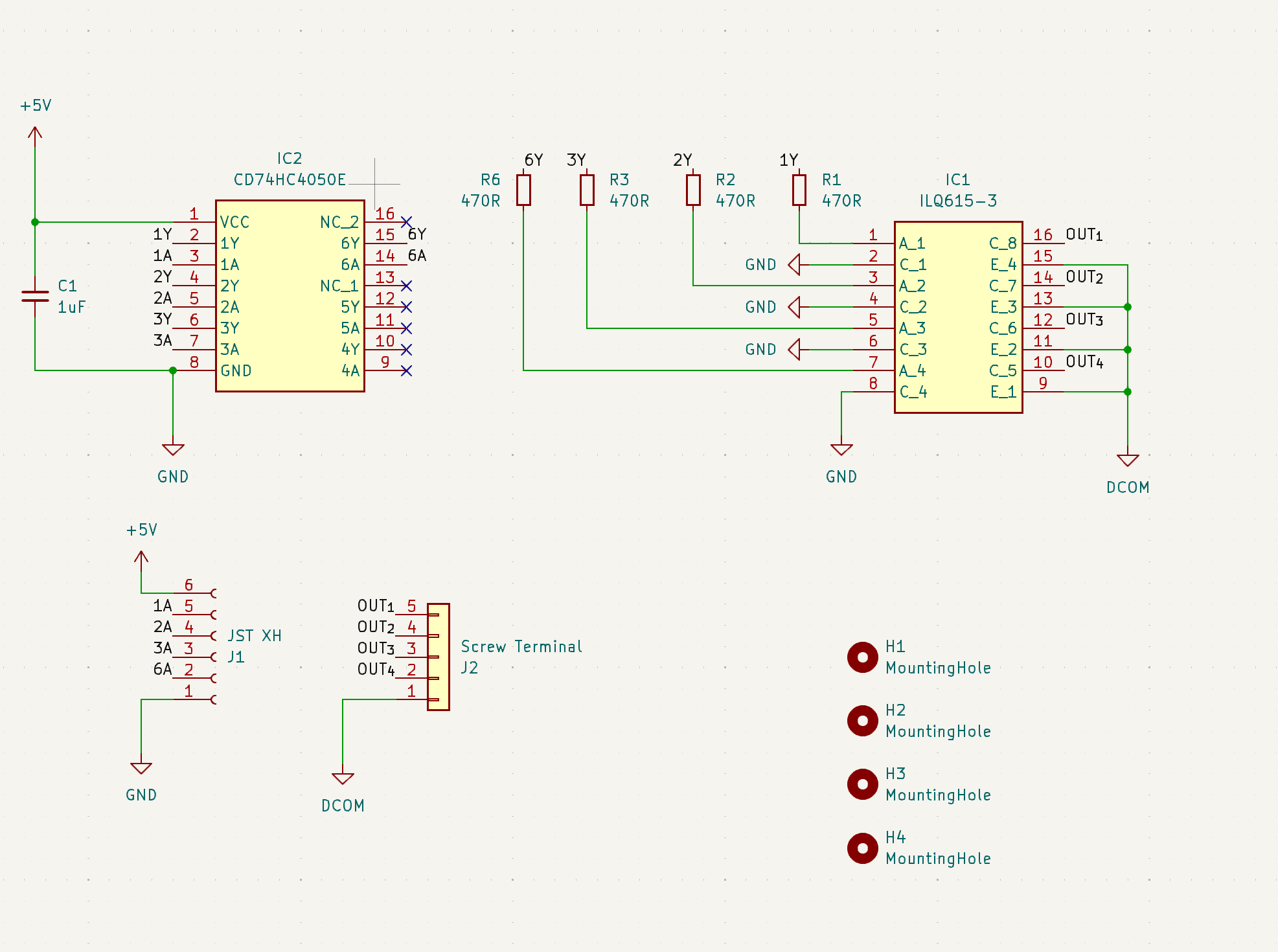
The board can be ordered from JLCPCB using the provided Gerber files. Simply upload the files, select your options, and you'll have your custom PCB in no time.
This project is shared under the Creative Commons License (CC BY-NC-ND): Non-Commercial, No Remix, Attribution Required. Contributions and modifications are welcome within these guidelines.
Designed by knight_rad.iant on Discord. For questions or discussions, feel free to join the CNC community and share your thoughts!
| Qty | Value | Footprint | References |
|---|---|---|---|
| 4 | 470R | Resistor_THT:R_Axial_DIN0207_L6.3mm_D2.5mm_P7.62mm_Horizontal | R1, R2, R3, R6 |
| 4 | MountingHole | MountingHole:MountingHole_3.2mm_M3_Pad | H1, H2, H3, H4 |
| 1 | 1uF | Capacitor_THT:C_Disc_D5.1mm_W3.2mm_P5.00mm | C1 |
| 1 | CD74HC4050E | Mouser:DIP794W53P254L1930H508Q16N | IC2 |
| 1 | ILQ615-3 | Mouser:DIP762W56P254L1992H470Q16N | IC1 |
| 1 | JST XH | Connector_JST:JST_XH_B6B-XH-AM_1x06_P2.50mm_Vertical | J1 |
| 1 | Screw Terminal | TerminalBlock:TerminalBlock_bornier-5_P5.08mm | J2 |
ikmitche/OSHE-RecycleBot
The Home of the Open Source Hardware Enterprise's RecycleBot Project

akladnig/CamperVan
- CamperVan Design and Arduino Circuit Design - Campervan Design Overview - Dashboard App - Electrical System - Sensors - Circuit Design - Battery and voltage monitoring - Voltage Divider Design - Low Pass Filter - TODO


samyk/magspoof
A portable device that can spoof/emulate any magnetic stripe, credit card or hotel card "wirelessly", even on standard magstripe (non-NFC/RFID) readers.

fossasia/pslab-scripts
Pocket Science Lab - Scripts for Sensor Experiments


willem-pennings/balancing-cube
A cube that balances itself in a corner or edge using reaction wheels
It measures 40 × 45 mm and has 2 copper layers, 1.6 mm thick.
13 parts, built around the CD74HC4050EG4 and ILQ615-3. The full list of its parts is on this page, with links to each part's symbol and footprint where PCBKit's library has them.
From the jrlomas/vfd-rat-king repository on GitHub, at the commit this page was made from: the board is kicad/vfd-rat-king.kicad_pcb and its schematic kicad/vfd-rat-king.kicad_sch. PCBKit opens the board in the browser, with nothing to install.
Its repository states no licence, so its author keeps all rights: ask jrlomas before reusing the design.