4 layers160 × 100 mm
V2.1 board ecar isolated
Jonny999999/electric-kart
Firmware and pcb's for custom built electric kart
116 parts

 Jonny999999/throttle-tune
onversion of an old gasoline lawn tractor to an electric vehicle
Throttle tune is an open-source printed circuit board by Jonny999999, from the Jonny999999/throttle-tune repository on GitHub. It is a 2-layer board of 74.7 × 69.1 mm with 51 parts on 40 nets, routed with 279 tracks and 10 vias.
It is built around the ATMEGA8A-PU, LM358N and LM7805, with the BC547 and IRF5305PBF among its other parts. Its parts include 13 capacitors, 12 resistors, 10 connectors, 3 ICs and 2 transistors. It belongs with the robots and motor control boards and the AVR (ATmega, ATtiny) boards of this library.


A microcontroller-based board with a PWM-based analog output (RC filter + buffer) to emulate a DAC. The goal is to improve throttle response and add configurable driving modes to cheap BLDC motor controllers (e.g. 3000 W BLDC "go-kart kit" controllers).
Currently it is used in the electric Kettcar conversion with a 3000 W BLDC drive, this board fixes the controller’s unusable throttle mapping and makes the vehicle smooth and controllable adding a lot of flexibility.
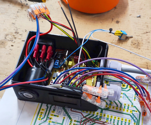
Control box with the custom pcb connected between throttle and motor controller
Contains: PCB, key switch, battery indicator, several UI switches
Cheap BLDC controllers (such as KT-style 3000 W kits) have several issues:
Using only the original setup makes smooth low-speed driving or child-friendly operation nearly impossible
The Throttle Tune board sits between the analog throttle pedal (or handle) and the motor controller.
It rescales, filters, and manipulates the signal (fading, modes...) while adding safety and convenience features.
pcb_throttle-tune/export/schematic.pdf
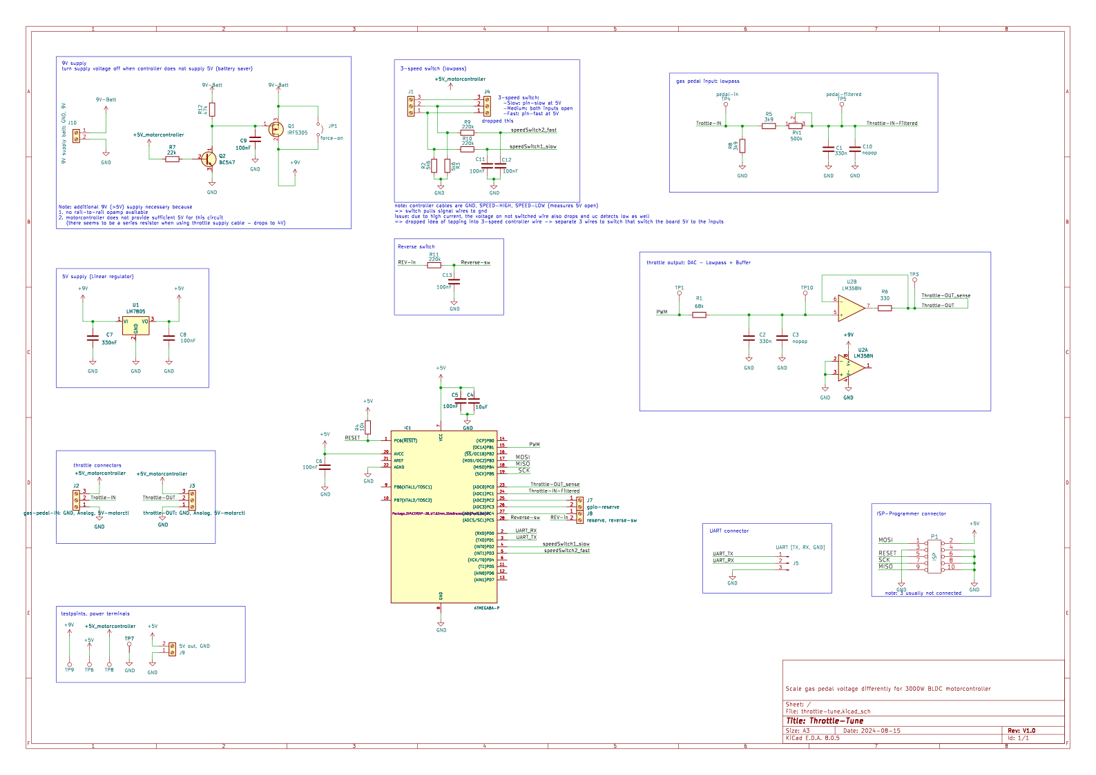
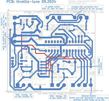
Documentation: pfusch.zone/electric-kettcar
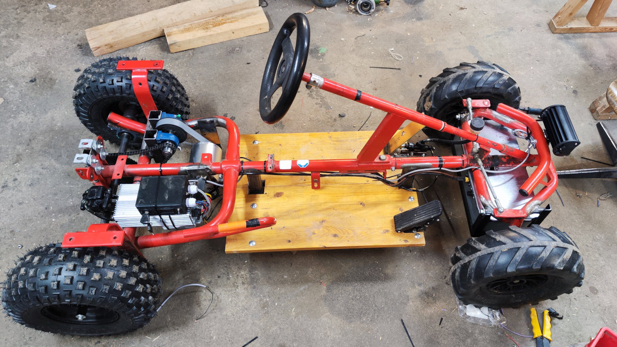
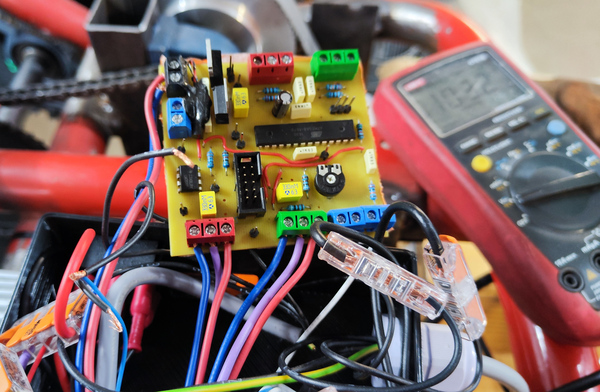
Wiring of PCB between pedal and controller (right) and the finished vehicle (left).
Documentation: pfusch.zone/electric-lawn-tractor
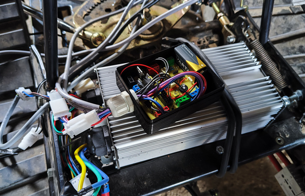
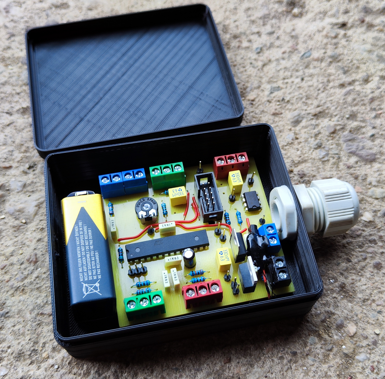
Throttle Tune board inside in box on top of the motor controller, battery powered (earlier project - initial but temporary use).
pcb_throttle-tune/ – KiCad project, schematic, layout exportsfw_throttle-tune/ – AVR firmware (ATmega8)doc/images – photos of the build and control boxSee pcb_throttle-tune/export/layout.pdf for what needs to be connected to which terminals.
Several config options (macro variables) are defined at the top of main.c (see detailed comments).
These include controller start/max voltage, pedal min/max voltage, idle voltage, etc.
To calibrate:
DEBUG_UART_DEBUG_OUTPUT_ENABLEDmain.c accordingly, compile, flash, try againDriving modes are selected via 2 GPIO pins, each with its own config in the modeConfigs[] array.
Parameters can be tuned per mode using this struct:
//=============================
//==== Mode configuration =====
//=============================
typedef struct {
    const char *name;
    uint8_t maxPercent;     // percent of max possible speed applied at full throttle
    uint8_t maxPercentReverse;
    uint8_t beepCount;      // count beeped when entering this mode
    uint16_t rampUpStep;    // max duty increment per interval (max 1023)
    uint16_t rampUpIntervalMs; // note: must be larger than cycle time (consider when UART used alot)
    uint8_t pedalAverageWindowSize; // window size of the moving average to smooth pedal input (0 = disabled)
    // Future: pedal averaging, throttle curve, etc.
} kettcarConfig_t;
See comments in main.c and adjust as needed.
yay -S avr-gcc avr-libc makecd fw_throttle-tune/
makeConnect avr controller using USBASP V2.0 ISP programmer using the 10pin connector on the pcb
cd fw_throttle-tune/
make # compile firmware first
sudo make upload # flash to MCU via USBaspNote: Be sure to recompile before flashing, or you may upload an old build...
| Qty | Value | Footprint | References |
|---|---|---|---|
| 7 | 100nF | Capacitor_THT:C_Disc_D7.0mm_W2.5mm_P5.00mm | C5, C6, C8, C9, C11, C12, C13 |
| 3 | 220k | Resistor_THT:R_Axial_DIN0207_L6.3mm_D2.5mm_P10.16mm_Horizontal | R9, R10, R11 |
| 2 | 330n | Capacitor_THT:C_Disc_D8.0mm_W5.0mm_P5.00mm | C1, C2 |
| 2 | 3k9 | Resistor_THT:R_Axial_DIN0207_L6.3mm_D2.5mm_P10.16mm_Horizontal | R5, R8 |
| 2 | 5k6 | Resistor_THT:R_Axial_DIN0207_L6.3mm_D2.5mm_P10.16mm_Horizontal | R2, R3 |
| 2 | nopop | Capacitor_THT:C_Disc_D8.0mm_W5.0mm_P5.00mm | C3, C10 |
| 1 | 10k | Resistor_THT:R_Axial_DIN0207_L6.3mm_D2.5mm_P10.16mm_Horizontal | R4 |
| 1 | 10uF | Capacitor_THT:CP_Radial_D5.0mm_P2.50mm | C4 |
| 1 | 22k | Resistor_THT:R_Axial_DIN0207_L6.3mm_D2.5mm_P10.16mm_Horizontal | R7 |
| 1 | 3-speed-IN: COM, sw-fast, sw-slow | TerminalBlock:TerminalBlock_bornier-3_P5.08mm | J1 |
| 1 | 3-speed-OUT: COM, sw-fast, sw-slow | TerminalBlock:TerminalBlock_bornier-3_P5.08mm | J4 |
| 1 | 330 | Resistor_THT:R_Axial_DIN0207_L6.3mm_D2.5mm_P10.16mm_Horizontal | R6 |
| 1 | 330nF | Capacitor_THT:C_Disc_D8.0mm_W5.0mm_P5.00mm | C7 |
| 1 | 47k | Resistor_THT:R_Axial_DIN0207_L6.3mm_D2.5mm_P10.16mm_Horizontal | R12 |
| 1 | 500k | Potentiometer_THT:Potentiometer_Piher_PT-10-V10_Vertical | RV1 |
| 1 | 5V | Connector_PinHeader_1.00mm:PinHeader_1x01_P1.00mm_Vertical | TP6 |
| 1 | 5V controller | Connector_PinHeader_1.00mm:PinHeader_1x01_P1.00mm_Vertical | TP8 |
| 1 | 5V out, GND | TerminalBlock:TerminalBlock_bornier-2_P5.08mm | J9 |
| 1 | 68k | Resistor_THT:R_Axial_DIN0207_L6.3mm_D2.5mm_P10.16mm_Horizontal | R1 |
| 1 | 9V | Connector_PinHeader_1.00mm:PinHeader_1x01_P1.00mm_Vertical | TP9 |
| 1 | 9V supply batt: GND, 9V | TerminalBlock:TerminalBlock_bornier-2_P5.08mm | J10 |
| 1 | ATMEGA8A-P | Package_DIP:CERDIP-28_W7.62mm_SideBrazed_LongPads_Socket | IC1 |
| 1 | BC547 | Package_TO_SOT_THT_AKL:TO-92_Inline_Wide_CBE | Q2 |
| 1 | DAC | Connector_PinHeader_1.00mm:PinHeader_1x01_P1.00mm_Vertical | TP10 |
| 1 | GND | Connector_PinHeader_1.00mm:PinHeader_1x01_P1.00mm_Vertical | TP7 |
| 1 | IRF5305 | Package_TO_SOT_THT:TO-220-3_Vertical | Q1 |
| 1 | ISP | Connector_IDC:IDC-Header_2x05_P2.54mm_Vertical | P1 |
| 1 | LM358N | Package_DIP:DIP-8_W7.62mm_LongPads | U2 |
| 1 | LM7805 | Package_TO_SOT_THT:TO-220-3_Vertical | U1 |
| 1 | PWM | Connector_PinHeader_1.00mm:PinHeader_1x01_P1.00mm_Vertical | TP1 |
| 1 | Throttle-Out | Connector_PinHeader_1.00mm:PinHeader_1x01_P1.00mm_Vertical | TP3 |
| 1 | UART [TX, RX, GND] | Connector_PinHeader_2.54mm:PinHeader_1x03_P2.54mm_Vertical | J5 |
| 1 | force-on | Jumper_AKL:Jumper_P2.54mm_D0.7mm | JP1 |
| 1 | gas-pedal-IN: GND, Analog, 5V-motorctl | TerminalBlock:TerminalBlock_bornier-3_P5.08mm | J2 |
| 1 | gpio-reserve | TerminalBlock:TerminalBlock_bornier-2_P5.08mm | J7 |
| 1 | pedal-filtered | Connector_PinHeader_1.00mm:PinHeader_1x01_P1.00mm_Vertical | TP5 |
| 1 | pedal-in | Connector_PinHeader_1.00mm:PinHeader_1x01_P1.00mm_Vertical | TP4 |
| 1 | reserve, REVERSE-SW | TerminalBlock:TerminalBlock_bornier-2_P5.08mm | J8 |
| 1 | throttle-OUT: GND, Analog, 5V-motorctl | TerminalBlock:TerminalBlock_bornier-3_P5.08mm | J3 |
It measures 74.7 × 69.1 mm and has 2 copper layers, 1.6 mm thick.
51 parts, built around the ATMEGA8A-PU, LM358N, LM7805 and BC547. The full list of its parts is on this page, with links to each part's symbol and footprint where PCBKit's library has them.
From the Jonny999999/throttle-tune repository on GitHub, at the commit this page was made from: the board is pcb_throttle-tune/throttle-tune.kicad_pcb and its schematic pcb_throttle-tune/throttle-tune.kicad_sch. PCBKit opens the board in the browser, with nothing to install.
Its repository states no licence, so its author keeps all rights: ask Jonny999999 before reusing the design.
Jonny999999/electric-kart
Firmware and pcb's for custom built electric kart


phaenovum/RaspiCar
A model car equipped with a Raspberry Pi, intended for experimenting with tools and algorithms for autonomous navigation


jakeread/tesc
in-progress motor controller, towards accessible closed-loop control

EngLuizs/Fonte_Linear_12V
Fonte linear regulada ajustável (12V/1A) com telemetria digital integrada. Desenvolvida com ESP32, KiCad e PlatformIO para monitoramento local (LCD) e remoto (Web Server Wi-Fi).

