
2 layers100 × 100 mm
Explorer
anyshake/explorer
🌏 Detecting seismic wave using 3 geophones and 3-axis accelerometer, pack & send data to AnyShake Observer over RS232 / RS485 serial.
266 parts100

 Jonny999999/powerMonitor-esp32
Firmware and hardware for measuring voltage, current, and power using PZEM-004T modules with ESP32, and publishing the data via MQTT.
UART RS485 interface board is an open-source printed circuit board by Jonny999999, from the Jonny999999/powerMonitor-esp32 repository on GitHub. It is a 4-layer board of 68.6 × 27.9 mm with 18 parts on 7 nets, routed with 48 tracks and 6 vias.
It is built around the MAX3485ED. Its parts include 4 resistors, 4 connectors, 2 capacitors and 1 IC. It belongs with the interfaces and adapters and home automation and IoT boards and the ESP32 boards of this library.
This project documents a system for monitoring photovoltaic (PV) power production and household power consumption using ESP32 and PZEM-004T / PZEM-016 power sensors, with data published over MQTT.
Included in this repo:
The following screenshots show the resulting dashboard created using Node-RED where the sensor data is received via MQTT and stored in a database. The charts visualize all sensor values across multiple inverters and locations.
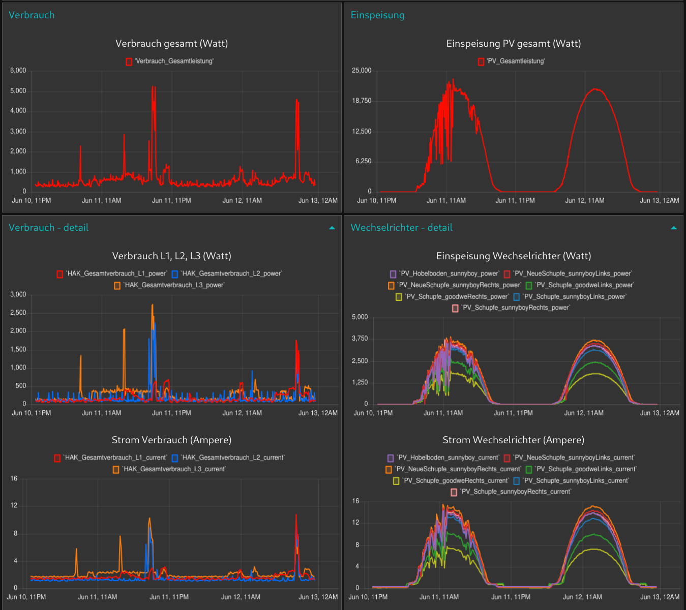
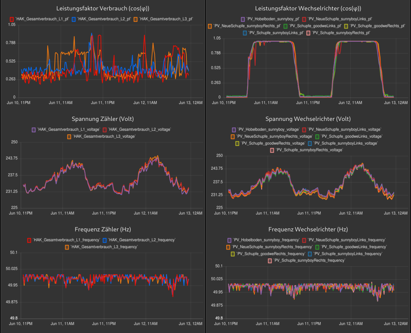
Below are a few example photos of the current wiring and hardware setup.
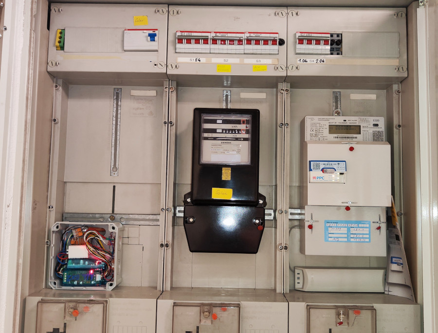
Used for measuring total consumption of the entire building. One module for each phase (L1, L2, L3).
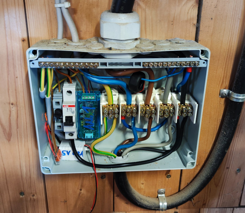
Each module is wired to one phase of a single inverter output.
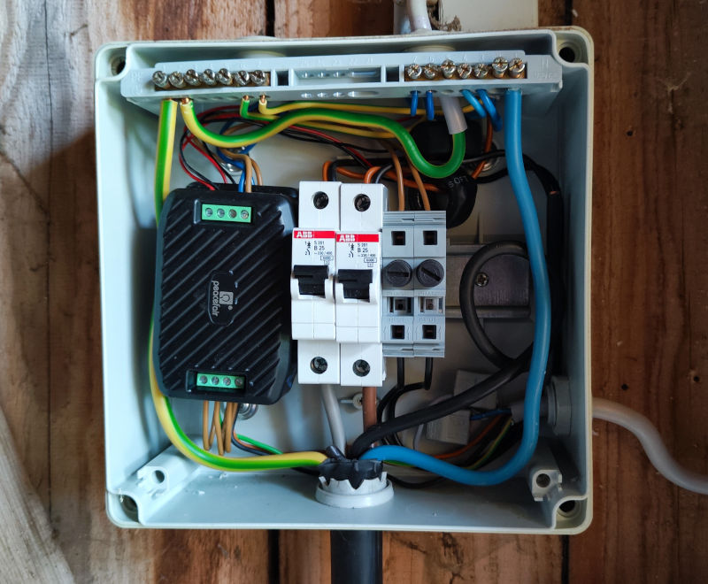
PZEM-016 modules connected via a shared RS485 bus and assigned separate Modbus addresses.
On the other side of a ~30 m 5×1.5 mm² power cable, an ESP32 with a custom RS485-to-UART PCB receives the data and publishes it via MQTT.
To interface the ESP32 with RS485-based PZEM-016 sensors, a small PCB based on the MAX3485 transceiver was created.
hardware/UART-RS485_interface-board/schematic.pdf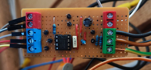
Firmware for reading multiple PZEM modules and publishing the values via MQTT.
Tested with ESP-IDF 5.3.
Make sure ESP-IDF 5.3 is sourced:
. /opt/esp-idf-v5.3/v5.3/esp-idf/export.sh
cd esp32_power-monitor
idf.py build flash monitorpower-meter.py)Utility script for directly configuring and reading PZEM modules using a USB-to-Serial adapter.
pip install pyserialpzem_tool.py:
Then run the script:
python3 pzem_tool.pyfirmware/ # Several ESP-IDF projects for all instances running
hardware/UART-RS485_interface-board/ # KiCad project for interface PCB
doc/images/ # photos and documentationmain/credentials.h which is not tracked in the repo.| Qty | Value | Footprint | References |
|---|---|---|---|
| 2 | GND, 3v3 | terminals_libJonny:ScrewTerminal_P5mm_2Pin_FP10x8 | J2, J3 |
| 1 | 100n | Capacitor_THT:C_Disc_D7.5mm_W5.0mm_P7.50mm | C1 |
| 1 | 10k | Resistor_THT:R_Axial_DIN0309_L9.0mm_D3.2mm_P15.24mm_Horizontal | R17 |
| 1 | 10uf | Capacitor_THT:CP_Radial_D8.0mm_P5.00mm | C2 |
| 1 | 120 | Resistor_THT:R_Axial_DIN0207_L6.3mm_D2.5mm_P2.54mm_Vertical | R36 |
| 1 | 3k3 | Resistor_THT:R_Axial_DIN0207_L6.3mm_D2.5mm_P10.16mm_Horizontal | R37 |
| 1 | 3k3 | Resistor_THT:R_Axial_DIN0207_L6.3mm_D2.5mm_P5.08mm_Vertical | R35 |
| 1 | 3v3 | Connector_PinHeader_2.54mm:PinHeader_1x01_P2.54mm_Vertical | TP6 |
| 1 | DIR | Connector_PinHeader_2.54mm:PinHeader_1x01_P2.54mm_Vertical | TP4 |
| 1 | MAX3485 | Package_DIP:DIP-8_W7.62mm_LongPads | U2 |
| 1 | RS-A | Connector_PinHeader_2.54mm:PinHeader_1x01_P2.54mm_Vertical | TP3 |
| 1 | RS-B | Connector_PinHeader_2.54mm:PinHeader_1x01_P2.54mm_Vertical | TP5 |
| 1 | RX | Connector_PinHeader_2.54mm:PinHeader_1x01_P2.54mm_Vertical | TP2 |
| 1 | TX | Connector_PinHeader_2.54mm:PinHeader_1x01_P2.54mm_Vertical | TP1 |
| 1 | [GND, A, B] RS485 (Sensor) | terminals_libJonny:ScrewTerminal_P5mm_3Pin_FP15x8 | J8 |
| 1 | [TX, DIR, RX] UART (ESP32) | terminals_libJonny:ScrewTerminal_P5mm_3Pin_FP15x8 | J1 |
| 1 | gnd | Connector_PinHeader_2.54mm:PinHeader_1x01_P2.54mm_Vertical | TP7 |
It measures 68.6 × 27.9 mm and has 4 copper layers, 1.6 mm thick.
18 parts, built around the MAX3485ED. The full list of its parts is on this page, with links to each part's symbol and footprint where PCBKit's library has them.
From the Jonny999999/powerMonitor-esp32 repository on GitHub, at the commit this page was made from: the board is hardware/UART-RS485_interface-board/UART-RS485_interface-board.kicad_pcb and its schematic hardware/UART-RS485_interface-board/UART-RS485_interface-board.kicad_sch. PCBKit opens the board in the browser, with nothing to install.
Its repository states no licence, so its author keeps all rights: ask Jonny999999 before reusing the design.
anyshake/explorer
🌏 Detecting seismic wave using 3 geophones and 3-axis accelerometer, pack & send data to AnyShake Observer over RS232 / RS485 serial.

hirakuni45/RX
Renesas RX Microcontroller, C++ framework, Library, Sample


emertcakir/OpenAirScope
Open-source air quality and environmental monitoring node with STM32H743 + ESP32-C3, LoRaWAN, RS485, USB-C, Li-ion charging, and multi-sensor support.


rmingon/rs485-spy-injector
RS485 Spy is an open-source hardware tool for real-time monitoring, logging, and testing of RS-485 networks

kim-xps12/m5stack_board_dynamixel_ttl_rs3485
When using this repository in your own environment, please import HY2.0-4P.kicadmod into the appropriate library. I import it into the global library so that it can be used from other projects as well.
