
2 layers

 jonathonlui/magsafe-trigger18
Schematic and PCB design for using MagSafe 2 power adapter to power other things
Magsafe trigger is an open-source printed circuit board by jonathonlui, from the jonathonlui/magsafe-trigger repository on GitHub. It is a 2-layer board of 40.3 × 21.5 mm with 12 parts on 7 nets, routed with 38 tracks and 26 vias.
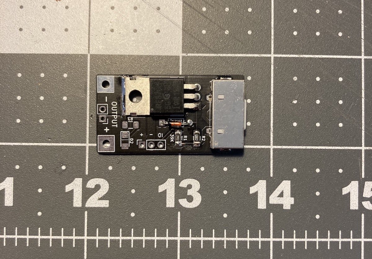
It is built around the IRF3708S-VB. Its parts include 6 connectors, 3 resistors, 2 diodes and 1 transistor. It belongs with the interfaces and adapters boards of this library.
Use a MagSafe 2 Power Adapter to power other devices.
Based on info from Macbook charger teardown from Ken Shirriff's blog (see section Operation of the charger and footnote 15 and 16)
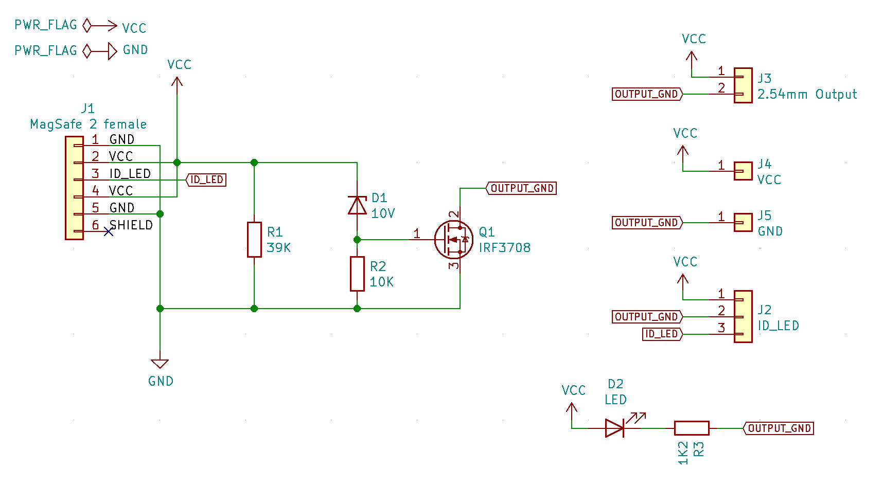
MagSafe power adapter output a low voltage until it detects about 39K Ohm load. The low voltage depends on the model and version of the MagSafe adapter and will be between 0.6V to 6V.
The Zener diode blocks current to the MOSFET gate until the voltage is above the Zener’s reverse breakdown voltage. Using a 10V Zener diode keeps the output off until the MagSafe adapter switches to full voltage.
Full voltage is 14.5V to 20V depending on MagSafe model. With the 10V Zener inline the gate voltage when full voltage is between 4.5V to 10V which is enough to fully turn on the MOSFET.
Without the MOSFET blocking current though the OUTPUT, any load on the OUTPUT will prevent the MagSafe power adapter from switch from low voltage to high voltage..
ID_LED pin is connected to a chip inside the the male connector. It is normally used by Apple laptops to read the type and id/serial number of power supply and to turn on and off the LEDS. It does not need to be used to trigger the full voltage
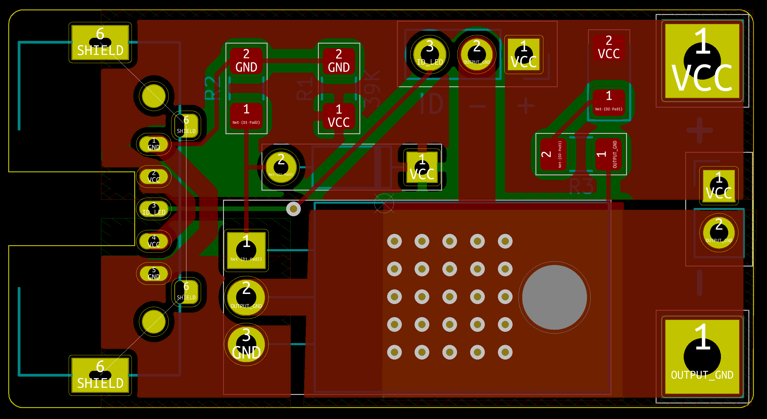
MagSafe jack footprint is based on manual measurements and probably needs tweaking for proper fit.
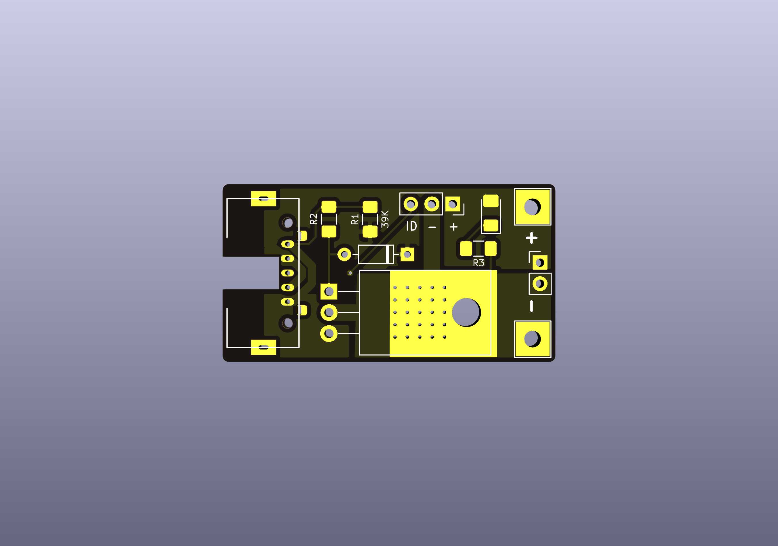
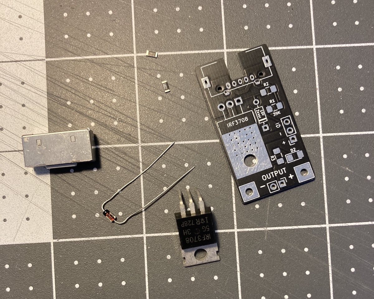
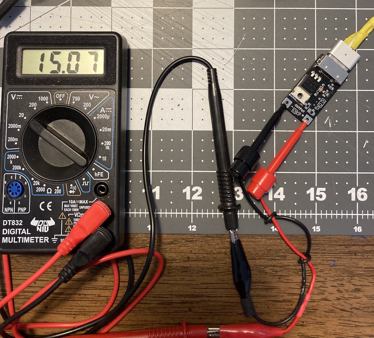
Plugging in a 45 W MagSafe 2 Power Adapter shows 15 V open circuit.
| Qty | Value | Footprint | References |
|---|---|---|---|
| 2 | MagSafe 2 female | magsafe-trigger:MagSafe_2_Female | J1, J1 |
| 1 | 10K | Resistor_SMD:R_1206_3216Metric_Pad1.42x1.75mm_HandSolder | R2 |
| 1 | 10V | Diode_THT:D_DO-35_SOD27_P7.62mm_Horizontal | D1 |
| 1 | 1K2 | Resistor_SMD:R_1206_3216Metric_Pad1.42x1.75mm_HandSolder | R3 |
| 1 | 2.54mm Output | Connector_PinHeader_2.54mm:PinHeader_1x02_P2.54mm_Vertical | J3 |
| 1 | 39K | Resistor_SMD:R_1206_3216Metric_Pad1.42x1.75mm_HandSolder | R1 |
| 1 | GND | TestPoint:TestPoint_THTPad_4.0x4.0mm_Drill2.0mm | J5 |
| 1 | ID_LED | Connector_PinSocket_2.54mm:PinSocket_1x03_P2.54mm_Vertical | J2 |
| 1 | IRF3708 | Package_TO_SOT_THT:TO-220-3_Horizontal_TabDown | Q1 |
| 1 | LED | LED_SMD:LED_1206_3216Metric_Pad1.42x1.75mm_HandSolder | D2 |
| 1 | VCC | TestPoint:TestPoint_THTPad_4.0x4.0mm_Drill2.0mm | J4 |
It measures 40.3 × 21.5 mm and has 2 copper layers, 1.6 mm thick.
12 parts, built around the IRF3708S-VB. The full list of its parts is on this page, with links to each part's symbol and footprint where PCBKit's library has them.
From the jonathonlui/magsafe-trigger repository on GitHub, at the commit this page was made from: the board is magsafe-trigger.kicad_pcb. PCBKit opens the board in the browser, with nothing to install.
Its repository states no licence, so its author keeps all rights: ask jonathonlui before reusing the design.


ujkhm/micro-generator-test-machine
ESP32 MPPT for micro-generator output measurement.

github-linguist/linguist
Language Savant. If your repository's language is being reported incorrectly, send us a pull request!


google/mozc-devices
Circuit diagrams and firmware source code for Gboard DIY keyboards