4 layers50 × 50 mm
ESP32-S3-testboard
Imdad2005/ESP32-S3-testboard
Custom 4-layer ESP32-S3 IoT testboard designed in KiCad 9, featuring USB-C, 3.3 V power regulation, environmental sensing, and QWIIC/SPI expansion.
42 parts1

 JonasLindinger/MicroPad2
Battery-efficient ESP32-S3 macro pad with a 2.9" e-paper display for controlling Home Assistant. Pages and per-key actions are configured in a web tool and pushed over MQTT — no reflashing for menu or key changes. WiFiManager onboarding, light-sleep power management.
MicroPad is an open-source printed circuit board by JonasLindinger, from the JonasLindinger/MicroPad repository on GitHub, published under the MIT licence. It is a 4-layer board of 89.5 × 96.8 mm with 72 parts on 80 nets, routed with 515 tracks and 68 vias.
It is built around the ESP32-S3-WROOM-1-N8, AP2112K-3.3 and BQ24075RGT, with the USBLC6-2SC6, 500ASSP1SM6QE and BLM21PG220SN1 among its other parts. Its parts include 17 diodes, 15 switches, 11 resistors, 10 capacitors and 8 connectors. It belongs with the lEDs and displays and home automation and IoT boards and the ESP32 boards of this library.


AI-assisted development — firmware, HA automation, config generator and docs were created with AI (LLM) help, reviewed and tested by the author. Provided as-is, without warranty; verify on your own hardware, don't use for safety-critical applications.
MicroPad is a small ESP32-S3 desk controller with a 2.9" e-paper display, a 3×4 key matrix, and a rotary encoder. It talks to Home Assistant over MQTT and shows clickable pages of your devices, media, scripts, scenes, and numbers. This repository contains the firmware, the Home Assistant automation generator, the web configurator, and the deployment/service assets.
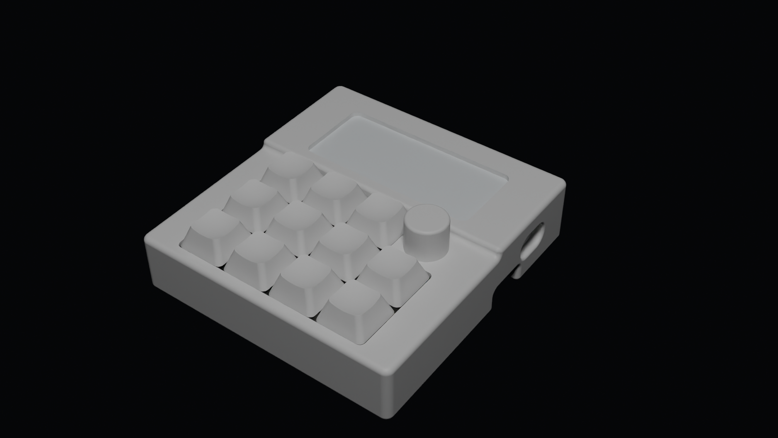
Case render — 3×4 key grid, rotary encoder, and the 2.9" e-paper display window.
Printable parts are in STL Files/ and the Blender source is
blender/MicroPad.blend.
192.168.0.100, the service user is micropad, and the
placeholder password is replace-me. Real Wi-Fi/MQTT credentials are entered
only through the on-device setup portal and stored in NVS.docs/hardware-acceptance.md.The Python dependency graph is locked: uv.lock is the resolved source of
truth, and requirements-lock.txt is its content-hash materialization (every
wheel pinned with sha256, regenerated with uv export --frozen). The build
backend is pinned exactly (setuptools==84.0.0). This freezes dependency
versions and content; it does not claim byte-identical builds, because
pip/setuptools release artifacts can still vary between environments. Generated
automation/payload artifacts are deterministic per configuration (see below).
Create a virtualenv and install the package and dev tools (Ubuntu/Debian shown):
python3 -m venv .venv
.venv/bin/pip install --requirement requirements-dev.txt
For a content-hash-pinned runtime install (every transitive dependency locked in
uv.lock and materialized as requirements-lock.txt with sha256 hashes)
instead use:
.venv/bin/pip install --requirement requirements-lock.txtRun the configurator locally for development (Flask dev server):
.venv/bin/python -m flask --app micropad.wsgi:app run --host 127.0.0.1 --port 8080Check it is healthy:
curl http://127.0.0.1:8080/healthz
# -> {"ok": true, "service": "micropad-configurator"}
For production, install the systemd service under /opt/micropad/app (root):
sudo ./scripts/setup.sh --enable-service
journalctl -u micropad.service -f
The on-device network setup and the build/flash workflow are described in
docs/firmware.md.
The firmware lives in firmware/ (MicroPad_HA_Controller.ino,
micropad_core.*, and protocol_contract.h). It is built with Arduino CLI 1.5.1,
ESP32 core 3.3.11, GxEPD2 1.6.9, ArduinoJson 7.4.3, and PubSubClient 2.8.
./scripts/install-arduino-toolchain.sh        # pin the exact toolchain
./scripts/compile-firmware.sh --print-matrix  # list the three pinned FQBNs
./scripts/compile-firmware.sh                 # compile all matrix FQBNs
See docs/firmware.md for the pin map, build/flash commands, the setup portal,
and sleep behaviour.
A single MQTT automation (id micropad_controller) turns micropad/event and
micropad/power publications into device actions and re-publishes the
authoritative micropad/pages/all, micropad/page/current, and micropad/keymap
retained payloads. The automation and the retained initial payloads are generated
by src/micropad/generator.py and are byte-identical for the same configuration.
You can deliver the generated automation two ways:
Both are covered in docs/home-assistant.md.
The Flask web configurator (src/micropad/app.py) validates your configuration,
lets you edit pages, key maps, and entity bindings in the browser, discovers
Home Assistant entities, and generates or uploads the automation.
GET /api/config — current public configuration (credentials redacted).POST /api/config — validate and save a configuration.POST /api/validate — validate without saving.POST /api/upload/api — deploy via the Home Assistant REST API.POST /api/upload/ssh — deploy via SFTP/SSH.GET /api/meta — contract version, the fourteen key IDs, actions, item types,
templates, and the default keymap.See docs/configurator.md for the pages editor, key editor, entity discovery,
and validation rules, and docs/deployment.md for install/update/logs/uninstall.
Licensed under the MIT License (Copyright (c) 2026 Jonas Lindinger). All content above is written in neutral English and uses only the placeholder values described in the Safety section.
| Qty | Value | Footprint | References |
|---|---|---|---|
| 12 | D | Diode_SMD:D_SMA | D4, D5, D6, D7, D8, D9, D10, D11, D12, D13, D14, D15 |
| 11 | SWITCH | Button_Switch_Keyboard:SW_Cherry_MX_1.00u_PCB | SW3, SW4, SW5, SW6, SW7, SW8, SW9, SW10, SW11, SW13, SW14 |
| 4 | 1uF | Capacitor_SMD:C_0805_2012Metric_Pad1.18x1.45mm_HandSolder | C9, C10, C13, C14 |
| 4 | Conn_01x02 | Jumper:SolderJumper-2_P1.3mm_Open_TrianglePad1.0x1.5mm | J9, J10, J11, J12 |
| 4 | MountingHole | MountingHole:MountingHole_3.2mm_M3_DIN965 | H1, H2, H3, H4 |
| 3 | 1,5k | Resistor_SMD:R_0805_2012Metric_Pad1.20x1.40mm_HandSolder | R14, R15, R16 |
| 3 | 10k | Resistor_SMD:R_0805_2012Metric_Pad1.20x1.40mm_HandSolder | R8, R10, R11 |
| 2 | 100n | Capacitor_SMD:C_0805_2012Metric_Pad1.18x1.45mm_HandSolder | C8, C15 |
| 2 | 4,7uF | Capacitor_SMD:C_0805_2012Metric_Pad1.18x1.45mm_HandSolder | C11, C12 |
| 2 | 5.1k | Resistor_SMD:R_0805_2012Metric_Pad1.20x1.40mm_HandSolder | R1, R2 |
| 2 | GREEN | LED_THT:LED_D3.0mm | D17, D19 |
| 1 | 1,8k | Resistor_SMD:R_0805_2012Metric_Pad1.20x1.40mm_HandSolder | R17 |
| 1 | 100 | Resistor_SMD:R_0805_2012Metric_Pad1.20x1.40mm_HandSolder | R12 |
| 1 | 10u | Capacitor_SMD:C_0805_2012Metric_Pad1.18x1.45mm_HandSolder | C7 |
| 1 | 1N5822 | Diode_THT:D_DO-201AD_P15.24mm_Horizontal | D1 |
| 1 | 220u | Capacitor_SMD:CP_Elec_6.3x7.7 | C1 |
| 1 | 2A | Fuse:Fuse_0805_2012Metric_Pad1.15x1.40mm_HandSolder | F1 |
| 1 | 330 | Resistor_SMD:R_0805_2012Metric_Pad1.20x1.40mm_HandSolder | R13 |
| 1 | 500ASSP1SM6QE | 500ASSP1SM6QE:SW_500ASSP1SM6QE | S1 |
| 1 | AP2112K-3.3 | Package_TO_SOT_SMD:SOT-23-5 | U6 |
| 1 | B2B-PH-K-S (Battery) | B2B-PH-K-S:JST_B2B-PH-K-S | J6 |
| 1 | BLM21PG220 | Inductor_SMD:L_0805_2012Metric_Pad1.05x1.20mm_HandSolder | FB1 |
| 1 | BLUE | LED_THT:LED_D3.0mm | D16 |
| 1 | BOOT | Button_Switch_THT:SW_PUSH_6mm_H9.5mm | SW2 |
| 1 | BQ24075RGT | Package_DFN_QFN:VQFN-16-1EP_3x3mm_P0.5mm_EP1.6x1.6mm | U1 |
| 1 | ESP32-S3-WROOM-1 | RF_Module:ESP32-S3-WROOM-1 | U3 |
| 1 | LOGO | LOGO | G*** |
| 1 | ORANGE | LED_THT:LED_D3.0mm | D18 |
| 1 | Programming header | Connector_PinHeader_2.54mm:PinHeader_2x03_P2.54mm_Vertical | J4 |
| 1 | RESET | Button_Switch_THT:SW_PUSH_6mm_H9.5mm | SW1 |
| 1 | RotaryEncoder_Switch | Rotary_Encoder:RotaryEncoder_Alps_EC11E-Switch_Vertical_H20mm | SW12 |
| 1 | SPI for E-Ink Display | Connector_PinHeader_2.54mm:PinHeader_1x08_P2.54mm_Vertical | J5 |
| 1 | USBLC6-2SC6 | Package_TO_SOT_SMD:SOT-23-6 | U2 |
| 1 | USB_C_Receptacle_USB2.0_16P | Connector_USB:USB_C_Receptacle_GCT_USB4085 | J2 |
It measures 89.5 × 96.8 mm and has 4 copper layers, 1.58 mm thick.
72 parts, built around the ESP32-S3-WROOM-1-N8, AP2112K-3.3, BQ24075RGT and USBLC6-2SC6. The full list of its parts is on this page, with links to each part's symbol and footprint where PCBKit's library has them.
From the JonasLindinger/MicroPad repository on GitHub, at the commit this page was made from: the board is PCB/MicroPad.kicad_pcb and its schematic PCB/MicroPad.kicad_sch. PCBKit opens the board in the browser, with nothing to install.
Its repository publishes it under the MIT licence: you may reuse it on that licence's terms (keep the author's notice, and for a copyleft licence share your changes alike).
Imdad2005/ESP32-S3-testboard
Custom 4-layer ESP32-S3 IoT testboard designed in KiCad 9, featuring USB-C, 3.3 V power regulation, environmental sensing, and QWIIC/SPI expansion.

alisarpaksoy/ESP32-S3-Testboard
Custom ESP32-S3 test board designed in KiCad with USB-C, Si7021 temperature/humidity sensor, Qwiic I2C connector, RGB LED, and GPIO headers.


n2048-creative-technology/butterflyeffect
Art installation: ESP32-S3 'leaf' PCBs with mmWave radar + TFT glitch-text display

ysaip07/KiCAD_Project
Personal PCB design projects using KiCad, reflecting a strong foundation in electronics design, component footprints, and PCB fabrication workflows.


