
2 layers98 × 27 mm

 jolau/VibrationDAQ8
Data Acquisition (DAQ) of the Analog Devices ADcmXL3021 vibration sensor.
ADcmXL3021 adapter is an open-source printed circuit board by jolau, from the jolau/VibrationDAQ repository on GitHub, published under the MPL-2.0 licence. It is a 2-layer board of 13 × 12.7 mm with 5 parts on 14 nets, routed with 75 tracks and 6 vias.
It is built around the DF12(3.0)-14DP-0.5V(86). Its parts include 3 connectors and 2 capacitors. It belongs with the interfaces and adapters boards of this library.
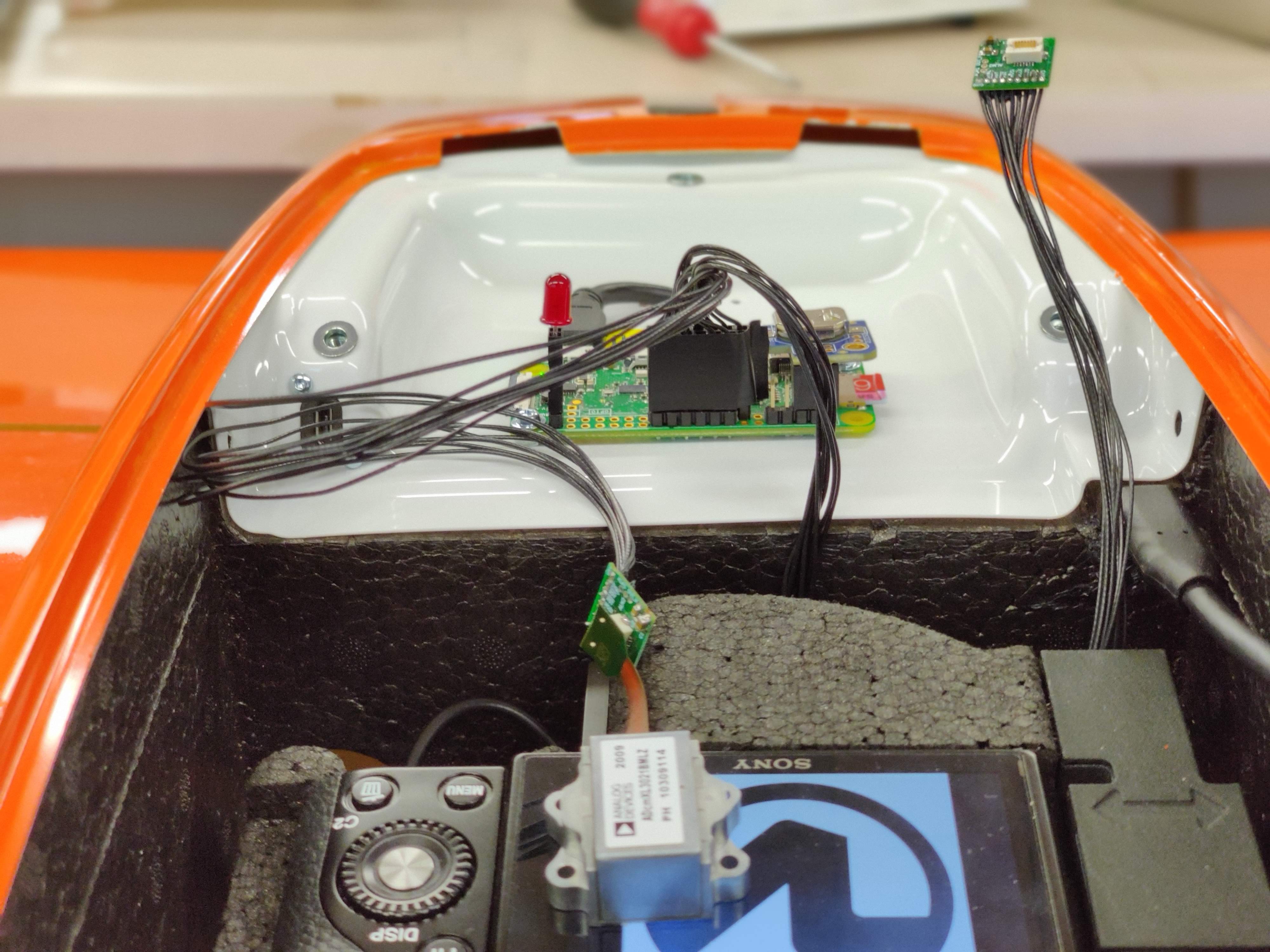
Data Acquisition (DAQ) of the Analog Devices ADcmXL3021 vibration sensor. The VibrationDAQ was developed as part of an internship at Wingtra by Jonas Lauener.
For any technical questions, please open an issue: https://github.com/jolau/VibrationDAQ/issues/new/choose
Copyright (c) 2020, Jonas Lauener & Wingtra AG


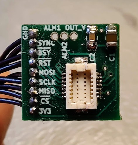
| pin | pin | ||
|---|---|---|---|
| RST 1 | 13 | ||
| BSY 1 | 15 | 16 | RST 2 |
| 3V3 | 17 | 18 | BSY 2 |
| MOSI | 19 | 20 | EMPTY |
| MISO | 21 | 22 | SYNC |
| SCLK | 23 | 24 | CE 1 |
| GND | 25 | 26 | CE 2 |
The vibration sensor only works on the main SPI pins (SPI0) of the Raspberry Pi - the other SPI ports don't support SPI mode 3.
The pins of the ADcmXL3021 vibration sensor can be accessed by using a custom adapter board. The PCB was created by using the software KiCad: KiCad project files
In case you want to setup your own VibrationDAQ on a Raspberry Pi:
cd VibrationDAQmkdir build & cd buildcmake ..sudo make installMake sure that you have enabled SPI.
You can use it now with vibration_daq_app [full path to config.yaml].
wget https://github.com/jbeder/yaml-cpp/archive/yaml-cpp-0.6.3.tar.gztar -xvf yaml-cpp-0.6.3.tar.gzcd yaml-cpp-yaml-cpp-0.6.3/mkdir buildcd buildcmake .. -DYAML_BUILD_SHARED_LIBS=ONsudo make installsudo systemctl enable [full path to vibration_daq.service file]enable with disable to disable service.Many thanks to the authors of the following libraries:
~/Documents/config.yaml to your requirements. Make sure that auto-start is enabled. If it's the first time you use it, test it by running it manually: vibration_daq_app [full path to config.yaml]If the status led is enabled in config, it will glow when running:
Short primer on the syntax of yaml: https://learnxinyminutes.com/docs/yaml/
Setting the right decimation_factor is crucial for getting meaningful data. Choose it according to the maximum vibration frequency you're expecting.
Of course, the decimation factor also affects the predefined FIR filters i.e. with a FACTOR_64, the LOW_PASS_10kHz is actually a 156 Hz low pass filter.
| decimation_factor | Effective Sample Rate, fS (SPS) | Effective FFT Bin Size, f_MIN (Hz) | Effective Maximum FFT Frequency, f_MAX (Hz) |
|---|---|---|---|
| FACTOR_1 | 220000 | 53.71094 | 110000 |
| FACTOR_2 | 110000 | 26.85547 | 55000 |
| FACTOR_4 | 55000 | 13.42773 | 27500 |
| FACTOR_8 | 27500 | 6.713867 | 13750 |
| FACTOR_16 | 13750 | 3.356934 | 6875 |
| FACTOR_32 | 6875 | 1.678467 | 3437.5 |
| FACTOR_64 | 3437.5 | 0.839233 | 1718.75 |
| FACTOR_128 | 1718.75 | 0.419617 | 859.375 |
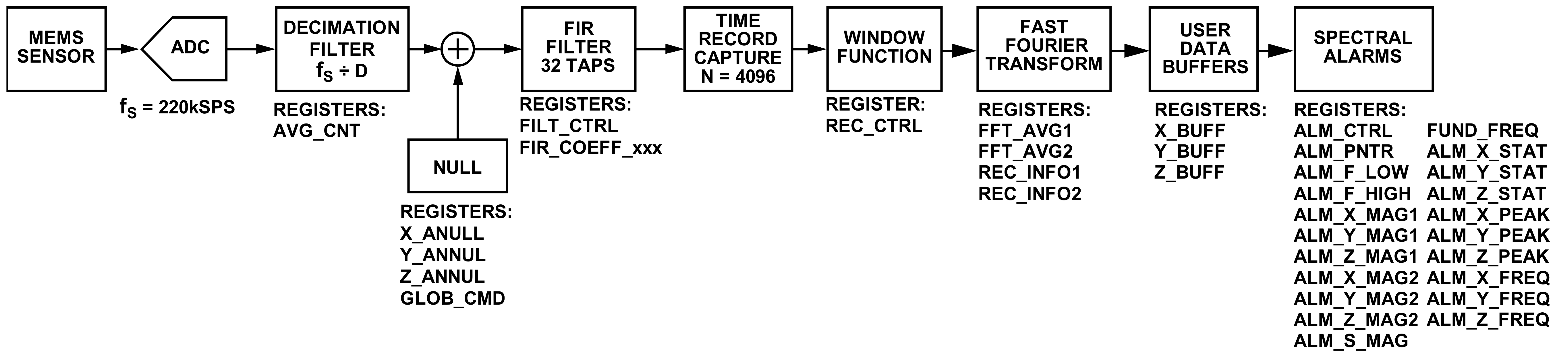
The spectral_avg_count determines the number of FFT records that the ADcmXL3021 averages when generating the final FFT result. Up to 255 records. Good for getting FFT measurements over longer time periods.
4096 samples / (220'000 sample rate / decimation_factor) * spectral_avg_count = record time [s]
4096 samples / (220000 sample rate / 64) * 255 = 303.84 seconds = 5.06 minutes
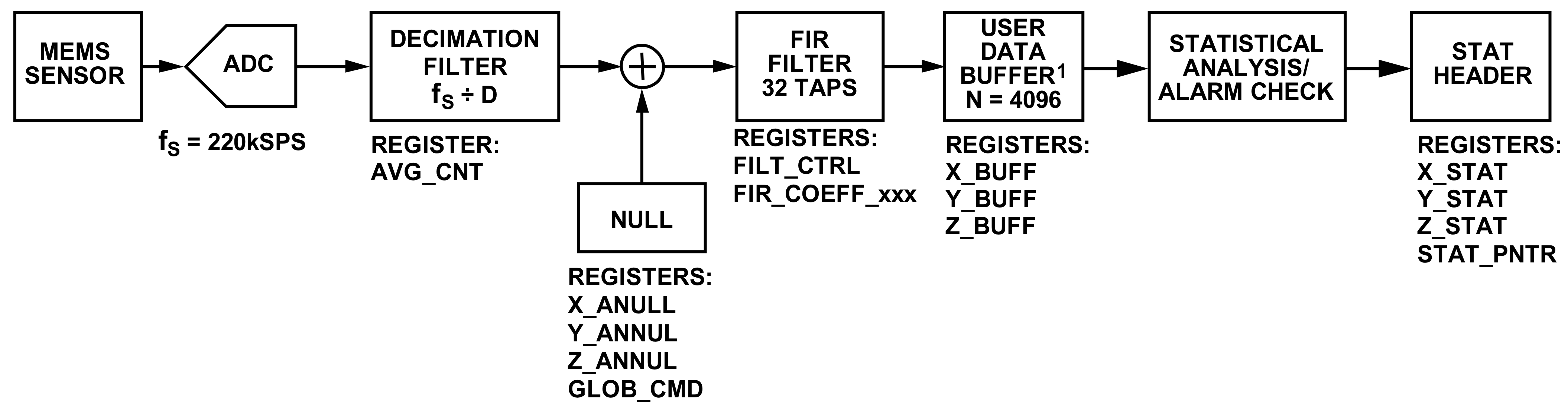
4096 samples / (220'000 sample rate / decimation_factor) = record time [s]
storage_directory: "/home/pi/Documents/"
recordings_count: 2 #number of recurring measurements, infinite if == 0
external_trigger: false # false: triggering over SPI;
                        # true: triggering over dedicated pin, useful for triggering multiple sensor at exact same time (connect them to same pin)
external_trigger_pin: 4 # only read if external_trigger == true
status_led: true # enable/disable status led, blinks everytime a vibration file is written
status_led_pin: 21  # only read if status_led == true
sensors:
  - name: sensor1 #will be used for logging and filenames
    busy_pin: 22 #BCM pin number
    reset_pin: 27 #BCM pin number
    spi_path: "/dev/spidev0.0"
    recording_mode: MFFT # MTC and MFFT supported
    MFFT_config: &mfftConfig #only read if recording_mode == MFFT
      decimation_factor: FACTOR_2 #supported: [FACTOR_1 = 0, FACTOR_2 = 1, FACTOR_4 = 2, FACTOR_8 = 3, FACTOR_16 = 4, FACTOR_32 = 5, FACTOR_64 = 6, FACTOR_128 = 7]
      fir_filter: CUSTOM #supported: [NO_FILTER, LOW_PASS_1kHz, LOW_PASS_5kHz, LOW_PASS_10kHz, HIGH_PASS_1kHz, HIGH_PASS_5kHz, HIGH_PASS_10kHz, CUSTOM]
      custom_filter_taps: [6, 21, 53, 107, 193, 316, 480, 686, 930, 1203, 1490, 1774, 2034, 2251, 2407, 2489, 2489, 2407, 2251, 2034, 1774, 1490, 1203, 930, 686, 480, 316, 193, 107, 53, 21, 6]
      spectral_avg_count: 2 # value between 1-255
      window_setting: HANNING #supported: [RECTANGULAR, HANNING, FLAT_TOP]
    MTC_config: #only read if recording_mode == MTC
        decimation_factor: FACTOR_2
        fir_filter: CUSTOM
        custom_filter_taps: [6, 21, 53, 107, 193, 316, 480, 686, 930, 1203, 1490, 1774, 2034, 2251, 2407, 2489, 2489, 2407, 2251, 2034, 1774, 1490, 1203, 930, 686, 480, 316, 193, 107, 53, 21, 6]
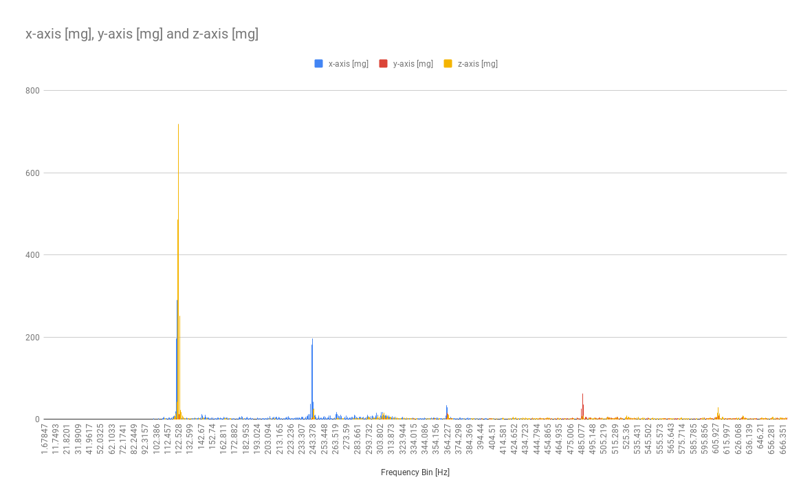
- name: sensor2The following data was collected on a self-made vibration bench. The bench consists of an unbalanced mass attached to an electrical motor.
| Qty | Value | Footprint | References |
|---|---|---|---|
| 1 | 10UF 25V | Capacitor_SMD:C_0805_2012Metric_Pad1.15x1.40mm_HandSolder | C1 |
| 1 | 1UF 25V | Capacitor_SMD:C_0805_2012Metric_Pad1.15x1.40mm_HandSolder | C2 |
| 1 | Aux Pin Header | Connector_PinHeader_1.27mm:PinHeader_1x03_P1.27mm_Vertical | J3 |
| 1 | DF12(3.0)-14DP-0.5V(86) | Connector_Hirose:Hirose_DF12(3.0)-14DP-0.5V(86) | J1 |
| 1 | Pin Header | Connector_PinHeader_1.27mm:PinHeader_1x09_P1.27mm_Vertical | J2 |
It measures 13 × 12.7 mm and has 2 copper layers, 0.8 mm thick.
5 parts, built around the DF12(3.0)-14DP-0.5V(86). The full list of its parts is on this page, with links to each part's symbol and footprint where PCBKit's library has them.
From the jolau/VibrationDAQ repository on GitHub, at the commit this page was made from: the board is ADcmXL3021_adapter/ADcmXL3021_adapter.kicad_pcb. PCBKit opens the board in the browser, with nothing to install.
Its repository publishes it under the MPL-2.0 licence: you may reuse it on that licence's terms (keep the author's notice, and for a copyleft licence share your changes alike).

joypad-ai/joypad-os
Universal controller firmware for building adapters, dongles, and custom controllers.

OLIMEX/OLINUXINO
OLINUXINO is Open Source / Open Hardware, low cost from EUR 24 Linux Industrial grade Single Board Computer capable to operate -25+85C

jamro/tiny-engineer
A small desktop robot that brings an AI coding assistant to life, physically acting out when it reads files, thinks, writes code, and finishes work.

hackclub/OnBoard
💡 Join 1,000 teenagers and make your first PCB with a $100 grant!


Luos-io/luos_engine
Open-source and real-time orchestrator for cyber-physical-systems, to easily design, test and deploy embedded applications and digital twins.