2 layers50.6 × 129 mm

 johnkok/pina1
Raspberry Pico-w Energy meter
Pina is an open-source printed circuit board by johnkok, from the johnkok/pina repository on GitHub, published under the Apache-2.0 licence. It is a 4-layer board of 147.3 × 96.5 mm with 77 parts on 77 nets, routed with 597 tracks and 100 vias.
It is built around the MIC24045-EIYFL-TR, SN74LXC8T245PW and BSS138, with the PM5022-100M-RC and SC0918 among its other parts. Its parts include 25 capacitors, 18 resistors, 8 diodes, 6 ICs and 3 inductors.


The aim of this project it to create a ultra precise energy meter based on INA228 TI's energy meter device. INA228 is a 20-bit energy meter device, with I2C host interface capable of measuring voltage/current/energy at sampling rates up to 20KHz. Device is connected with a Raspberry Pico W host acquiring the data from the I2C interface and communicating with the host through the WiFi interface using a TCP protocol. In addition, the Pico w module will be able to store IO level on DUT (Device Under Test) and transmit the data to the host application.
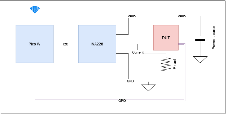
On the host side, a basic driver implemented for libsigrok for communicating with the Pico W firmware and propagating the data to sigrok suite. Patched version of sigrok library located at the following location: https://github.com/johnkok/libsigrok
| Qty | Value | Footprint | References |
|---|---|---|---|
| 16 | 0.1uF | Capacitor_SMD:C_0603_1608Metric_Pad1.08x0.95mm_HandSolder | C1, C3, C5, C6, C7, C9, C10, C11, C12, C13, C20, C21, C22, C23, C24, C25 |
| 4 | 1K | Resistor_SMD:R_0603_1608Metric_Pad0.98x0.95mm_HandSolder | R15, R16, R17, R18 |
| 4 | 1N5819 | Diode_SMD:D_SOD-123F | D1, D2, D3, D4 |
| 4 | 2K2 | Resistor_SMD:R_0603_1608Metric_Pad0.98x0.95mm_HandSolder | R1, R2, R10, R13 |
| 4 | LED | LED_SMD:LED_0603_1608Metric_Pad1.05x0.95mm_HandSolder | D5, D6, D7, D8 |
| 2 | 0 | Resistor_SMD:R_0603_1608Metric_Pad0.98x0.95mm_HandSolder | R5, R6 |
| 2 | 0.1 | Resistor_SMD:R_1206_3216Metric_Pad1.30x1.75mm_HandSolder | R11, R14 |
| 2 | 1 | Resistor_SMD:R_1206_3216Metric_Pad1.30x1.75mm_HandSolder | R3, R4 |
| 2 | 100 | Resistor_SMD:R_0603_1608Metric_Pad0.98x0.95mm_HandSolder | R9, R12 |
| 2 | 10nF | Capacitor_SMD:C_0603_1608Metric_Pad1.08x0.95mm_HandSolder | C18, C19 |
| 2 | 2.2uF | Capacitor_SMD:C_0805_2012Metric_Pad1.18x1.45mm_HandSolder | C14, C15 |
| 2 | 2K55 | Resistor_SMD:R_0603_1608Metric_Pad0.98x0.95mm_HandSolder | R7, R8 |
| 2 | 47pF | Capacitor_SMD:C_0603_1608Metric_Pad1.08x0.95mm_HandSolder | C16, C17 |
| 2 | BSS138 | Package_TO_SOT_SMD:SOT-23 | Q1, Q2 |
| 2 | G6B-1114P-US-DC5 | g6b:RELAY_G6B_1114 | K1, K2 |
| 2 | INA228 | Package_SO:VSSOP-10_3x3mm_P0.5mm | U3, U4 |
| 2 | MIC24045-EIYFL-TR | g6b:CONV_MIC24045-EIYFL-TR | U5, U6 |
| 2 | PM5022-100M-RC | Inductor_SMD:L_Bourns_SDR1806 | L2, L3 |
| 1 | 100uF | Capacitor_SMD:CP_Elec_8x11.9 | C2 |
| 1 | 12V-DC | Connector_BarrelJack:BarrelJack_GCT_DCJ200-10-A_Horizontal | J1 |
| 1 | 1uF | Capacitor_SMD:C_0603_1608Metric_Pad1.08x0.95mm_HandSolder | C4 |
| 1 | 330uF | Inductor_SMD:L_12x12mm_H6mm | L1 |
| 1 | 330uF | Capacitor_SMD:CP_Elec_8x11.9 | C8 |
| 1 | LM2575-5.0BU | Package_TO_SOT_SMD:TO-263-5_TabPin3 | U2 |
| 1 | LogicInputs | Connector_PinHeader_2.54mm:PinHeader_2x09_P2.54mm_Vertical | J2 |
| 1 | PM1_VBUS | Connector:Banana_Jack_1Pin | H1 |
| 1 | PM1_VIN_N | Connector:Banana_Jack_1Pin | H3 |
| 1 | PM1_VIN_P | Connector:Banana_Jack_1Pin | H2 |
| 1 | PM2_VBUS | Connector:Banana_Jack_1Pin | H4 |
| 1 | PM2_VIN_N | Connector:Banana_Jack_1Pin | H6 |
| 1 | PM2_VIN_P | Connector:Banana_Jack_1Pin | H5 |
| 1 | PS1_GND | Connector:Banana_Jack_1Pin | H8 |
| 1 | PS1_OUT | Connector:Banana_Jack_1Pin | H7 |
| 1 | PS2_GND | Connector:Banana_Jack_1Pin | H10 |
| 1 | PS2_OUT | Connector:Banana_Jack_1Pin | H9 |
| 1 | SC0918 | g6b:MODULE_SC0918 | A1 |
| 1 | SN74LXC8T245PW | Package_SO:TSSOP-24_4.4x7.8mm_P0.65mm | U1 |
It measures 147.3 × 96.5 mm and has 4 copper layers, 4.69 mm thick.
77 parts, built around the MIC24045-EIYFL-TR, SN74LXC8T245PW, BSS138 and PM5022-100M-RC. The full list of its parts is on this page, with links to each part's symbol and footprint where PCBKit's library has them.
From the johnkok/pina repository on GitHub, at the commit this page was made from: the board is HW/pina/pina.kicad_pcb and its schematic HW/pina/pina.kicad_sch. PCBKit opens the board in the browser, with nothing to install.
Its repository publishes it under the Apache-2.0 licence: you may reuse it on that licence's terms (keep the author's notice, and for a copyleft licence share your changes alike).

dg1vs/Transputer-Teensy-Link
A family of practical, Ethernet-connected link interfaces for classic INMOS transputer systems, based on the Teensy 4.1.

N1UGK/PCUI_Public
Collection of Programs and Utilities for the Pocket Computer Universal Interface

N1UGK/RetroLink_Public
RetroLink connects a standard POTS (Plain Old Telephone Service) analog telephone to the Internet over Wi-Fi, allowing peer-to-peer calling between devices and retro telephony interfacing.

BitDogLab/BitDogLab
Open-source educational hardware for embedded systems, programming, electronics, and physical computing.

c0de111/tinta
Battery-powered e-paper sign: room signage, sensor graphs, home automation, or anything over Wi-Fi. Wakes by real-time clock, NFC tap, or button. Raspberry Pi Pico W firmware, custom PCB, and 3D-printed case included.

gatasConspicuity/gatas
eConspicuity with support for ADS-L, OGN, FLARM, FANET for General Aviation
