2 layers24.4 × 24.4 mm
OSO SWAT B1
joeycastillo/Sensor-Watch
A board replacement for the classic Casio F-91W wristwatch
39 parts2.1k

 joeycastillo/Sensor-Watch2.1k
A board replacement for the classic Casio F-91W wristwatch
OSO SWAT C1 is an open-source printed circuit board by joeycastillo, from the joeycastillo/Sensor-Watch repository on GitHub. It is a 4-layer board of 24.4 × 24.4 mm with 40 parts on 64 nets, routed with 587 tracks and 81 vias.
It is built around the MIC5365-3.3YC5-TR, EVP-BB1AAB000 and QBLP655-RGB. Its parts include 9 capacitors, 9 resistors, 2 ICs, 2 diodes and 2 transistors. It belongs with the SAM D and SAM boards of this library.


The Sensor Watch is a board replacement for the classic Casio F-91W wristwatch. It is powered by a Microchip SAM L22 microcontroller with built-in segment LCD controller. You can write your own programs for the watch using the provided watch library, program the watch over USB using the built-in UF2 bootloader, and then install the board in your existing watch case to run your own software on your wrist.
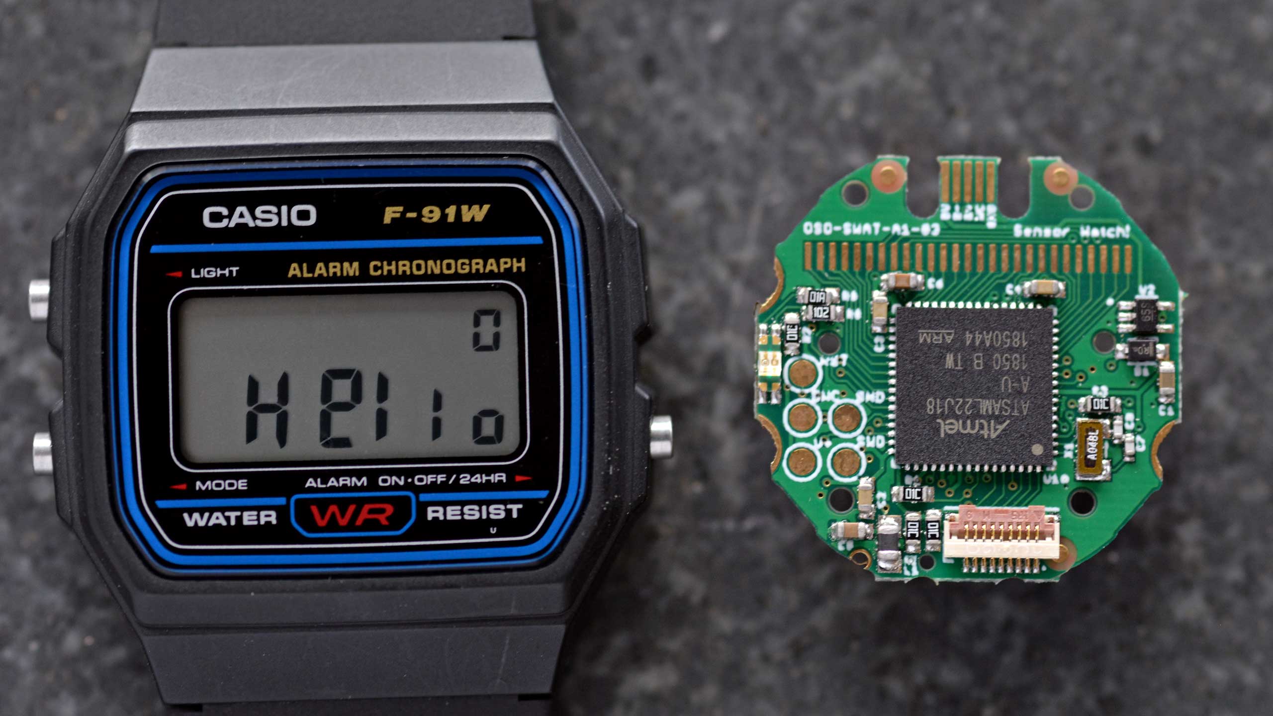
Features:
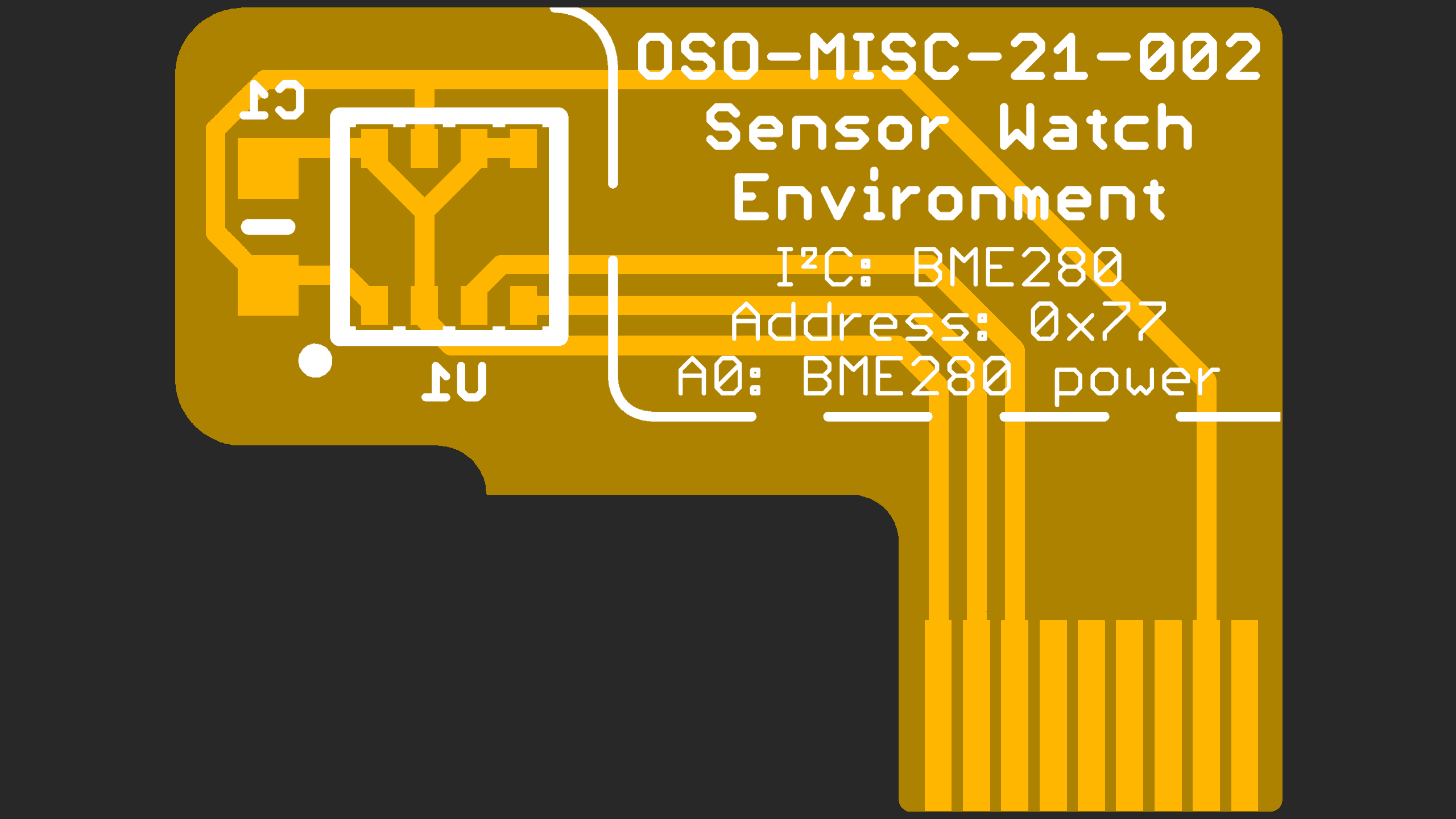
You may have noticed that there are no sensors on this board. That is by design: rather than pick sensors for you, the goal is to add a tiny flexible PCB with the sensors YOU want, and interface them over the nine-pin connector. The connector provides the following options for power and connectivity:
| Pin | Digital | Interrupt | Analog | I2C | SPI | UART | PWM | Ext. Wake |
|---|---|---|---|---|---|---|---|---|
| A0 | PB04 | EIC/EXTINT[4] | ADC/AIN[12] | — | — | — | — | — |
| SCL | — | — | — | SCL SERCOM1[1] | — | — | — | — |
| SDA | — | — | — | SDA SERCOM1[0] | — | — | — | — |
| A1 | PB01 | EIC/EXTINT[1] | ADC/AIN[9] | — | SCK SERCOM3[3] | RX SERCOM3[3] | TC3[1] | — |
| A2 | PB02 | EIC/EXTINT[2] | ADC/AIN[10] | — | MOSI SERCOM3[0] | TX or RX SERCOM3[0] | TC2[0] | RTC/IN[1] |
| A3 | PB03 | EIC/EXTINT[3] | ADC/AIN[11] | — | CS SERCOM3[1] | RX SERCOM3[1] | TC2[1] | — |
| A4 | PB00 | EIC/EXTINT[0] | ADC/AIN[8] | — | MISO SERCOM3[2] | TX or RX SERCOM3[2] | TC3[0] | RTC/IN[0] |
These tiny “sensor boards” have a set outline, and the available area for your electronics is quite small (5.7 × 5.7 × 1 mm). Still, this is plenty of room for an environmental sensor, MEMS accelerometer or magnetometer and a couple of decoupling capacitors. Note that you will likely be limited to QFN and LGA type parts; SOICs are too large, and even SSOP packages are generally too thick. You can find reference designs for several sensor boards in the PCB/Sensor Boards directory within this repository.
The watch library in this repository is very work-in-progress, but it should allow you to get started. To create a new project, copy the “starter-project” folder in the apps folder, and write your code in the app.c file.
You will need to install the GNU Arm Embedded Toolchain to build projects for the watch. The watch library has been tested with the 9-2019-q4-major version and the 10.3-2021.07 versions. If you're using Debian or Ubuntu, it should be sufficient to apt install gcc-arm-none-eabi.
To build your project, open your terminal and navigate to the project's make folder, then type make.
To install the project onto your Sensor Watch board, plug the watch into your USB port and double tap the tiny Reset button on the back of the board. You should see the LED light up red and begin pulsing. (If it does not, make sure you didn’t plug the board in upside down). Once you see the “WATCHBOOT” drive appear on your desktop, type make install. This will convert your compiled program to a UF2 file, and copy it over to the watch.
If you just want to make minor modifications and use existing code, start with the movement directory. You can build the default watch firmware with:
cd movement/make
make
Then copy movement/make/build/watch.uf2 to your watch. If you'd like to modify which faces are built, see movement_config.h.
You may want to test out changes in the emulator first. To do this, you'll need to install emscripten, then run:
cd movement/make
emmake make
python3 -m http.server -d build-sim
Finally, visit watch.html to see your work.
| Name | Color | Schematic | Gerbers |
|---|---|---|---|
| Sensorwatch Lite | RED | PCB/Main Boards/OSO-SWAT-B1 | OSO-SWAT-B1-03 |
| Sensorwatch | GREEN | OSO-SWAT-A1-05 (Eagle format) | ? |
| Sensorwatch Pro | TBD | TBD | TBD |
Different components of the project are licensed differently, see LICENSE.md.
| Qty | Value | Footprint | References |
|---|---|---|---|
| 5 | TestPoint | TestPoint:TestPoint_Pad_D1.5mm | TP2, TP3, TP4, TP5, TP6 |
| 4 | 10K | Resistor_SMD:R_0201_0603Metric | R1, R2, R3, R4 |
| 4 | MICROBUILDER_TESTPOINTROUND1.5MM | OSO-SWAT-A1-05:MICROBUILDER_TESTPOINT_ROUND_1.5MM | TP1, TP8, TP9, TP10 |
| 3 | 1uF | Capacitor_SMD:C_0603_1608Metric | C5, C6, C9 |
| 2 | 0.1uF | Capacitor_SMD:C_0603_1608Metric | C3, C4 |
| 2 | 100 | Resistor_SMD:R_0603_1608Metric | R7, R8 |
| 2 | 22pf | Capacitor_SMD:C_0402_1005Metric | C7, C8 |
| 1 | 0.1uF | Capacitor_SMD:C_0201_0603Metric | C2 |
| 1 | 10K 0.1% | Resistor_SMD:R_0603_1608Metric | R11 |
| 1 | 10K THERM | Resistor_SMD:R_0603_1608Metric | R10 |
| 1 | 10uF | Capacitor_SMD:C_0603_1608Metric | C1 |
| 1 | 10uH | Inductor_SMD:L_0805_2012Metric | L1 |
| 1 | 14 mH | OSO-SWAT-A1-05:ELT3KN | L2 |
| 1 | 1K | Resistor_SMD:R_0603_1608Metric | R6 |
| 1 | ATSAML22J18A-MUT | OSO-SWAT-A1-05:QFN64_9X9MC_MCH | U1 |
| 1 | Crystal | Crystal:Crystal_SMD_3215-2Pin_3.2x1.5mm | X1 |
| 1 | EVP-BB1AAB000 | OSO-SWAT-A1-05:SW_EVP-BB1AAB000 | RESET0 |
| 1 | FH19C-9S-0.5SH_10_ | OSO-SWAT-A1-05:FH19C9S05SH10 | J2 |
| 1 | LOGO | LOGO | G*** |
| 1 | MIC5365-3.3YC5-TR | OSO-SWAT-A1-05:SOT65P210X110-5N | U2 |
| 1 | QBLP655-RGB | OSO-SWAT-A1-05:LED_QBLP655_RGB | D2 |
| 1 | Q_NMOS_GSD | Package_TO_SOT_SMD:SOT-523 | Q2 |
| 1 | Q_Photo_NPN | Resistor_SMD:R_0603_1608Metric | Q1 |
| 1 | SCHOTTKY | OSO-SWAT-A1-05:SOD-323F | D1 |
| 1 | SENSOR-WATCH-USB | OSO-SWAT-A1-05:CASIO-F91W-OUTLINE-USB | U$2 |
joeycastillo/Sensor-Watch
A board replacement for the classic Casio F-91W wristwatch

joeycastillo/Sensor-Watch
A board replacement for the classic Casio F-91W wristwatch

joeycastillo/Sensor-Watch
A board replacement for the classic Casio F-91W wristwatch

joeycastillo/Sensor-Watch
A board replacement for the classic Casio F-91W wristwatch

joeycastillo/Sensor-Watch
A board replacement for the classic Casio F-91W wristwatch

joeycastillo/Sensor-Watch
A board replacement for the classic Casio F-91W wristwatch


Prajwal-sahyadri-ECE/-Optimized-Powersupply-design-
A highly detailed PCB to maintain an power supply for a defined hardware architecture specifically for ICS system


Glaubinator/Radio-Telescope-RCA
Radio Telescope System for 1 GHz to 2 GHz Operation

RubenVoell/iceduino
The basic idea behind this project is to create a simple breakout of an ICE40 FPGA with some LEDs and Buttons to interact with the FPGA and enough resources to run a simple softcore, like a small RISC-V core.

kcuzner/usb-led-controller
This is an LED controller for the lights that came with my In-Win A1 Mini-ITX Tower. It came with a simple 12V RGB LED strip, rather than the now-standard WS2812 addressable LED strips that are so common in today's PCs.

It measures 24.4 × 24.4 mm and has 4 copper layers, 0.61 mm thick.
40 parts, built around the MIC5365-3.3YC5-TR, EVP-BB1AAB000 and QBLP655-RGB. The full list of its parts is on this page, with links to each part's symbol and footprint where PCBKit's library has them.
From the joeycastillo/Sensor-Watch repository on GitHub, at the commit this page was made from: the board is PCB/Main Boards/OSO-SWAT-C1/OSO-SWAT-C1.kicad_pcb and its schematic PCB/Main Boards/OSO-SWAT-B1/OSO-SWAT-B1-jig/OSO-SWAT-B1-jig-generated.kicad_sch. PCBKit opens the board in the browser, with nothing to install.
Its repository states no licence, so its author keeps all rights: ask joeycastillo before reusing the design.