2 layers135.3 × 51 mm

 joakimsk/vibration-trigger
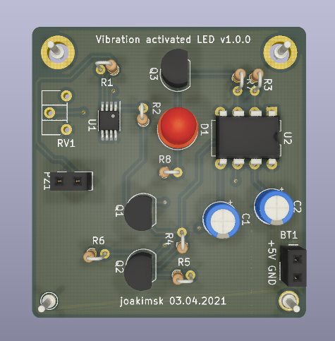
Vibration trigger circuit, to turn on a device for 30 seconds, resettable so that it remains on if vibration continues.
Full circuit is an open-source printed circuit board by joakimsk, from the joakimsk/vibration-trigger repository on GitHub, published under the Unlicense licence. It is a 2-layer board of 43.2 × 40.6 mm with 23 parts on 15 nets, routed with 70 tracks and 6 vias.
It is built around the LM386, NE555 and BC548, with the BC557 among its other parts. Its parts include 8 resistors, 3 transistors, 2 capacitors, 2 ICs and 1 diode.


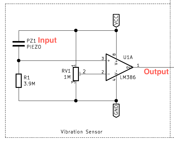
We use a Piezoelectric element with an operational amplifier (low power amplifier, LM386) to detect small movements. Sensitivity is controlled with potentiometer RV1.
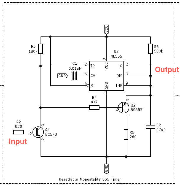
A monostable 555-timer gets triggered, and can be continuously reset, to maintain stable output signal.
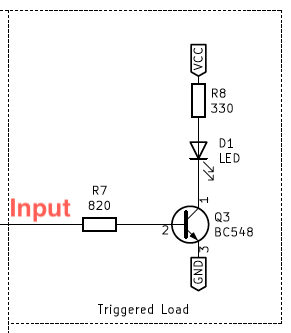
The output signal is in this case, driving a LED, but could be used to activate external devices, for example, the purpose of which this was made, an off-the-shelf GPS tracker.
Power supply should probably be 5v regulated... So consider using LM7805 or alternatives. I think a USB power supply connected to a 12v unregulated lead battery should be ok, 5-5.4 volts.
Schematic as PDF available here
Circuit consists of three components, which I try to explain here.
Latest revision 1.0.0 (first complete prototype).
Top plane is VCC (+5v), bottom plane is GND.
Mounting is supposed to be with 2x 3mm screw, 1x 2mm screw, 1x 1mm screw (just to test hole sizes).
Full PCB dimensions should be 43.18mm x 40.64mm.
The piezoelectric element needs to be well secured to the vibrating thing, be it your boat engine, your plane or your car. It can very well be a piezoelectric speaker.
The high voltage generated when a piezoelectric crystal is exposed to mechanical load, is compared using LM386 low power amplifier (Voltage Comparator configuration), to an adjustable reference voltage up to VCC (+5v).
I think I ended up with using the LM386 because it had more gain than a standard operational amplifier, but I cannot remember fully. The breadboard edition was tested a year ago.
The trigger signal from last component is used to reset a monostable 555 timer. It should toggle output high and take roughly 30 seconds due to size of R6 and C2 before output is low. It is resettable, by activating Q2, which drains C2 when triggered. This means the output signal will be stable, and can be kept high under prolonged vibrations.
The load is a placeholder for your important equipment. In this example, Q3 turns on LED D1 when input signal is high. Feel free to replace this component with whatever you want to turn on. This is supposed to turn on power to an off-the-shelf GPS tracker.
See xlsx for an attempt at BOM.
I wanted to track small boats without electric system, using battery power. The vibration from the outboard engine would activate the off-the-shelf GPS tracker, and keep it running while the boat is moving, but turn off when it is standing still. There is a bit of power consumption when disabled, but much less than keeping the GPS running all the time.
| Qty | Value | Footprint | References |
|---|---|---|---|
| 2 | 820 | Resistor_THT:R_Axial_DIN0204_L3.6mm_D1.6mm_P1.90mm_Vertical | R2, R7 |
| 2 | BC548 | Package_TO_SOT_THT:TO-92_Inline | Q1, Q3 |
| 1 | 0.01uF | Capacitor_THT:CP_Radial_D5.0mm_P2.50mm | C1 |
| 1 | 180k | Resistor_THT:R_Axial_DIN0204_L3.6mm_D1.6mm_P1.90mm_Vertical | R3 |
| 1 | 1M | Potentiometer_THT:Potentiometer_ACP_CA6-H2,5_Horizontal | RV1 |
| 1 | 260 | Resistor_THT:R_Axial_DIN0204_L3.6mm_D1.6mm_P1.90mm_Vertical | R5 |
| 1 | 3.9M | Resistor_THT:R_Axial_DIN0204_L3.6mm_D1.6mm_P1.90mm_Vertical | R1 |
| 1 | 330 | Resistor_THT:R_Axial_DIN0204_L3.6mm_D1.6mm_P1.90mm_Vertical | R8 |
| 1 | 47uF | Capacitor_THT:CP_Radial_D5.0mm_P2.50mm | C2 |
| 1 | 4k7 | Resistor_THT:R_Axial_DIN0204_L3.6mm_D1.6mm_P1.90mm_Vertical | R4 |
| 1 | 580k | Resistor_THT:R_Axial_DIN0204_L3.6mm_D1.6mm_P1.90mm_Vertical | R6 |
| 1 | 5v | Connector_PinSocket_2.54mm:PinSocket_1x02_P2.54mm_Vertical | BT1 |
| 1 | BC557 | Package_TO_SOT_THT:TO-92_Inline | Q2 |
| 1 | LED | LED_THT:LED_D5.0mm | D1 |
| 1 | LM386 | Package_SO:MSOP-8-1EP_3x3mm_P0.65mm_EP1.68x1.88mm | U1 |
| 1 | NE555 | Package_DIP:DIP-8_W7.62mm | U2 |
| 1 | PIEZO | Connector_PinSocket_2.54mm:PinSocket_1x02_P2.54mm_Vertical | PZ1 |
The 19 most common of 23 parts.
It measures 43.2 × 40.6 mm and has 2 copper layers, 1.6 mm thick.
23 parts, built around the LM386, NE555, BC548 and BC557. The full list of its parts is on this page, with links to each part's symbol and footprint where PCBKit's library has them.
From the joakimsk/vibration-trigger repository on GitHub, at the commit this page was made from: the board is pcb/full_circuit.kicad_pcb. PCBKit opens the board in the browser, with nothing to install.
Its repository publishes it under the Unlicense licence: you may reuse it on that licence's terms (keep the author's notice, and for a copyleft licence share your changes alike).

zxinfo-diy-electronics/zx-talkman
DIY Speech Interface for ZX Spectrum & ZX81 published in Ny Elektronik 1984 issue 10 page 36

ExploreEmbedded/8051_DevelopmentBoard
Design files and sample code for 8051 development Ultra Boards

alvaroalea/all-spectrum-clones
Schematic of a 8bit computer, clone of Sinclair ZX Spectrum

e-cite/arduino-ehz-diag
Circuit, PCB and software for a smart meter (EHZ EDL-21) diagnosis tool based on Arduino UNO

matiescobar2023/Automatica-y-Maquinas-Electricas
Repositorio para publicar los avances del proyecto


Roshan-khatri78/Electronics-Projects-KiCad-
A collection of my KiCad projects and PCB designs. These projects reflect my learning journey in electronics and PCB design.