4 layers72.2 × 70 mm

 jimmo/cpld-cpu16
A simple CPU implemented by discrete CPLD components.
Cpld cpu is an open-source printed circuit board by jimmo, from the jimmo/cpld-cpu repository on GitHub, published under the MIT licence. It is a 4-layer board of 259.1 × 198.1 mm with 441 parts on 505 nets, routed with 4,868 tracks and 933 vias.
Its parts include 209 resistors, 131 diodes, 53 capacitors, 16 connectors and 14 ICs. It belongs with the fPGA and programmable logic boards and the FPGA and CPLD boards of this library.
This is a project to create a demonstration CPU that is simple enough to be able to watch its execution but also able to do something almost useful.
It was inspired by the following five projects:
In particular the CPU design (ISA and architecture) is inspired by Fourbit, Tiny CPU, and especially MPU, while the exploded design and "LEDs everywhere" is inspired by the Megaprocessor and monster6502. While nowhere near as capable as monster6502 or the Megaprocessor, it is definitely much more budget-friendly! And it can still compute prime numbers (video) and drive APA102 LED strips.
Also, while not a direct inspiration to this project, it's absolutely worth linking to Breadboard 8-bit computer, by Ben Eater which is a wonderful series about a similar project.
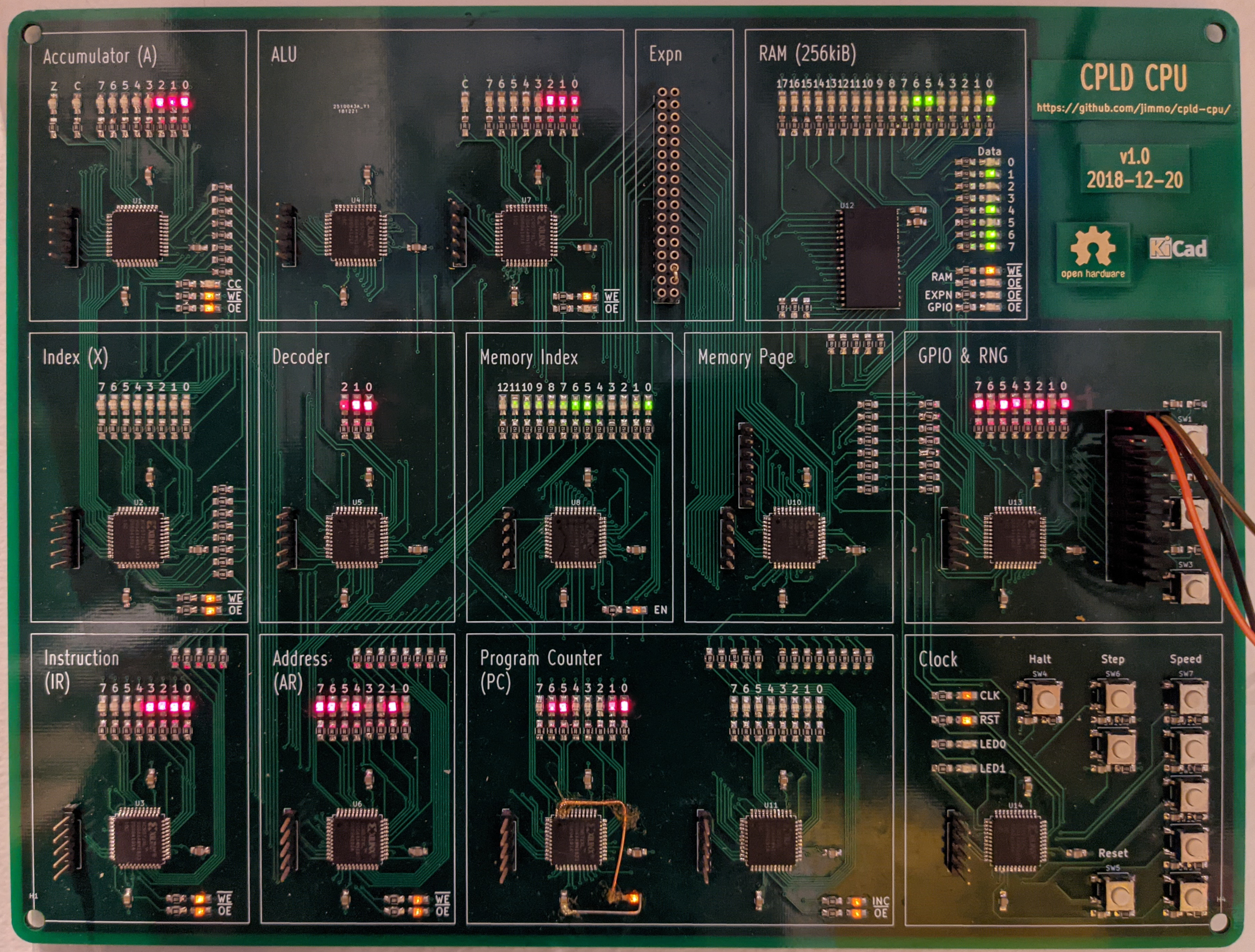
This idea started when I was teaching an introduction to "how CPUs work", and wanted something tangible to show my students. The goal is to show how simple logic circuits (i.e. starting with AND and OR gates, flip flops, and a clock) can work together to do computation. No magic required.
Initially I planned to exactly replicate the Fourbit (possibly upgraded to 8-bit), but had trouble sourcing the 74181 ALU. I found a XC9572XL CPLD development board in my board collection and considered replicating the 74181 on that. CPLDs are really useful for a project like this because they do not require external flash for configuration. You can use them almost as a complete drop-in replacement. However, at this point if you're not constraining yourself to using exactly 74xx series parts, then there are several simplifications you can make in the Fourbit design.
So I set about designing a CPU where each functional component is its own CPLD. In some ways this is similar to designing a soft-CPU for an FPGA, but with the additional constraint that signals between components actually need to go via physical pins. For an 8-bit CPU, this uses up a lot of pins very quickly.
For a fun side-quest, I wrote a logic simulator that allows a logic circuit to be defined in Python, and simulated, much the same way that Verilator can simulate an HDL file. This allowed me to test and iterate on some different designs, including an exact clone of the MCPU design. Additionally the simulator allows me to stay closer to my original goal of being able to describe every logic gate, although some shortcuts were taken.
The final design expands on the MCPU design, including 13-bit addressing, an index register, two-byte instruction encoding, a primitive MMU allowing addressing up to 1MiB of physical RAM, and memory-mapped IO. The memory is von Neumann, allowing for RAM and ROM to share the same bus. The simulator allowed some programs to be written and tested, including an assembler supporting some macro commands.
Once that was working, I translated each Python component into VHDL, and tested it on the CPLD breakout board. For example, here's the decoder (Python and VHDL). The most difficult part of this process, and possibly the whole project, was uploading the gateware to the CPLD. In order to keep the design simple, the clock is generated by a ring oscillator in the clock CPLD, which is a terrible idea in general but works well here.
Finally, I designed a schematic and PCB layout, which mostly involved laying out 131 LEDs (and their current limiting resistors). Rather than putting both RAM and ROM into the design, it just has a single RAM chip. This means that it has no persistent program storage, and the program needs to be loaded by an external programmer (implemented using some spare pins on the memory controller).
It's a four-layer PCB and can be assembled by hand with an iron or hot air. The CPLDs are TQFP and the LEDs and resistors are all 0805.
Other than occasionally being used for teaching, I mostly keep it mounted on the wall with the clock speed set to ~5Hz, forever computing prime numbers. It's quite mesmerizing to watch!
The instruction set is heavily inspired by MCPU. See their project description and blog post for more information. The main extension is the addition of the index register (X) as well as a jump-non-zero.
A = A nor [mem + X]
A = A + [mem + X]
[mem + X] = A
Jump if carry not set.
X = X nor [X]
X = X + [mem]
[mem] = X
Jump if zero flag not set.
These are supported by the assembler and generate a sequence of real instructions.
A = 0
A = [mem]
A = ~A
A = A - [mem + X]
X = 0
X = [mem]
X = ~X
X = X - [mem]
Unconditional jump
Jump if carry flag set
Jump if zero flag set
A = A << 1
A = A + 1
A = A - 1
A = A & [mem + X]
A = A | [mem + X]
A = ~(A & [mem + X])
A = ~(A ^ [mem + X])
A = A ^ [mem + X]
Sets the current memory page
Infinite loop
(Simulator only) prints A to stdout
There's a MicroPython script that can load a assembled binary via the serial programming interface (header is next to the memory controller).
| Qty | Value | Footprint | References |
|---|---|---|---|
| 131 | LED_Small | LEDs:LED_0805_HandSoldering | D1, D10, D11, D100, D101, D102, D103, D104, D105, D106, D107, D108, D109, D110, D111, D112 +115 |
| 110 | 2k | Resistors_SMD:R_0805_HandSoldering | R10, R11, R12, R100, R101, R102, R103, R104, R105, R106, R115, R116, R117, R118, R119, R120 +94 |
| 66 | 470 | Resistors_SMD:R_0805_HandSoldering | R107, R108, R109, R110, R111, R112, R113, R114, R123, R124, R125, R126, R127, R128, R129, R130 +50 |
| 53 | 100n | Capacitors_SMD:C_0805_HandSoldering | C1, C2, C10, C11, C12, C13, C14, C15, C16, C17, C18, C19, C20, C21, C22, C23 +37 |
| 21 | 1.2k | Resistors_SMD:R_0805_HandSoldering | R1, R2, R3, R160, R161, R162, R163, R164, R165, R166, R167, R168, R169, R170, R171, R172 +5 |
| 12 | 10k | Resistors_SMD:R_0805_HandSoldering | R189, R190, R191, R196, R197, R202, R203, R204, R205, R206, R207, R208 |
| 4 | MountingHole | Mounting_Holes:MountingHole_4.3mm_M4 | H1, H2, H3, H4 |
| 1 | ALU | Pin_Headers:Pin_Header_Straight_1x05_Pitch2.54mm | J7 |
| 1 | ALU | Housings_QFP:TQFP-44_10x10mm_Pitch0.8mm | U7 |
| 1 | AR | Housings_QFP:TQFP-44_10x10mm_Pitch0.8mm | U6 |
| 1 | AR | Pin_Headers:Pin_Header_Straight_1x05_Pitch2.54mm | J6 |
| 1 | AXM | Pin_Headers:Pin_Header_Straight_1x05_Pitch2.54mm | J4 |
| 1 | Acc | Housings_QFP:TQFP-44_10x10mm_Pitch0.8mm | U1 |
| 1 | Acc | Pin_Headers:Pin_Header_Straight_1x05_Pitch2.54mm | J1 |
| 1 | BTN0 | Buttons_Switches_SMD:SW_SPST_B3S-1000 | SW1 |
| 1 | BTN1 | Buttons_Switches_SMD:SW_SPST_B3S-1000 | SW2 |
| 1 | BTN2 | Buttons_Switches_SMD:SW_SPST_B3S-1000 | SW3 |
| 1 | CY62138FV30LL | Housings_SSOP:TSOP-II-32_21.0x10.2mm_Pitch1.27mm | U12 |
| 1 | Clock | Pin_Headers:Pin_Header_Straight_1x05_Pitch2.54mm | J16 |
| 1 | Clock | Housings_QFP:TQFP-44_10x10mm_Pitch0.8mm | U14 |
| 1 | Conn_01x07 | Pin_Headers:Pin_Header_Straight_1x07_Pitch2.54mm | J15 |
| 1 | Conn_02x14_Odd_Even | Pin_Headers:Pin_Header_Straight_2x14_Pitch2.54mm | J12 |
| 1 | Conn_02x17_Odd_Even | Pin_Headers:Pin_Header_Straight_2x17_Pitch2.54mm | J14 |
| 1 | Dec | Pin_Headers:Pin_Header_Straight_1x05_Pitch2.54mm | J5 |
| 1 | Decoder | Housings_QFP:TQFP-44_10x10mm_Pitch0.8mm | U5 |
| 1 | GPIO | Pin_Headers:Pin_Header_Straight_1x05_Pitch2.54mm | J13 |
| 1 | GPIO_RNG | Housings_QFP:TQFP-44_10x10mm_Pitch0.8mm | U13 |
| 1 | Halt | Buttons_Switches_SMD:SW_SPST_B3S-1000 | SW4 |
| 1 | IR | Pin_Headers:Pin_Header_Straight_1x05_Pitch2.54mm | J3 |
| 1 | IR | Housings_QFP:TQFP-44_10x10mm_Pitch0.8mm | U3 |
| 1 | Index | Pin_Headers:Pin_Header_Straight_1x05_Pitch2.54mm | J8 |
| 1 | KicadLogo | Symbols:Symbol_KiCAD-Logo_CopperAndSilkScreenTop | S1 |
| 1 | Multiplexer | Housings_QFP:TQFP-44_10x10mm_Pitch0.8mm | U4 |
| 1 | OSHWLogo | CPLD_CPU_Symbols:OSHW-Logo2_14.6x12mm_Copper_Top | S2 |
| 1 | PC_H | Housings_QFP:TQFP-44_10x10mm_Pitch0.8mm | U11 |
| 1 | PC_H | Pin_Headers:Pin_Header_Straight_1x05_Pitch2.54mm | J11 |
| 1 | PC_L | Housings_QFP:TQFP-44_10x10mm_Pitch0.8mm | U9 |
| 1 | PC_L | Pin_Headers:Pin_Header_Straight_1x05_Pitch2.54mm | J9 |
| 1 | Page | Pin_Headers:Pin_Header_Straight_1x05_Pitch2.54mm | J10 |
| 1 | RAM_Index | Housings_QFP:TQFP-44_10x10mm_Pitch0.8mm | U8 |
| 1 | RAM_Page | Housings_QFP:TQFP-44_10x10mm_Pitch0.8mm | U10 |
| 1 | Reset | Buttons_Switches_SMD:SW_SPST_B3S-1000 | SW5 |
| 1 | S0 | Buttons_Switches_SMD:SW_SPST_B3S-1000 | SW7 |
| 1 | S1 | Buttons_Switches_SMD:SW_SPST_B3S-1000 | SW11 |
| 1 | S2 | Buttons_Switches_SMD:SW_SPST_B3S-1000 | SW8 |
| 1 | S3 | Buttons_Switches_SMD:SW_SPST_B3S-1000 | SW12 |
| 1 | S4 | Buttons_Switches_SMD:SW_SPST_B3S-1000 | SW9 |
| 1 | Step 1 | Buttons_Switches_SMD:SW_SPST_B3S-1000 | SW6 |
| 1 | Step 8 | Buttons_Switches_SMD:SW_SPST_B3S-1000 | SW10 |
| 1 | X | Housings_QFP:TQFP-44_10x10mm_Pitch0.8mm | U2 |
| 1 | X | Pin_Headers:Pin_Header_Straight_1x05_Pitch2.54mm | J2 |
It measures 259.1 × 198.1 mm and has 4 copper layers, 1.6 mm thick.
441 parts. The full list of its parts is on this page, with links to each part's symbol and footprint where PCBKit's library has them.
From the jimmo/cpld-cpu repository on GitHub, at the commit this page was made from: the board is hardware/cpld-cpu.kicad_pcb. PCBKit opens the board in the browser, with nothing to install.
Its repository publishes it under the MIT licence: you may reuse it on that licence's terms (keep the author's notice, and for a copyleft licence share your changes alike).


OneAudio/OSVA
Open source versatible analyzer (24bits 1.536MSPS 2 Channels)

Duet3D/Duet3-Mini5plus
This repository also contains information in the Mini 2+ : a two driver expansion board for the Duet 3 mini 5+

espena/broadcast-clock
Digital precision studio/broadcast masterclock with WiFi configuration, acts as local NTP server with accurate GPS time sync.

baldengineer/Mega-IIe
Using the Mega II from a IIgs to make a Apple IIe compatible computer: The Mega IIe!