2 layers108.3 × 96.3 mm
Keyboard
hackclub/OnBoard
💡 Join 1,000 teenagers and make your first PCB with a $100 grant!
122 parts915

 jimbro1000/Dragon3264Keyboard4
Reproduction keyboard for Dragon 32 and 64 using modern switches
KeyboardTest is an open-source printed circuit board by jimbro1000, from the jimbro1000/Dragon3264Keyboard repository on GitHub, published under the MIT licence. It is a 2-layer board of 273.3 × 101.2 mm with 122 parts on 71 nets, routed with 688 tracks and 26 vias.
Its parts include 55 diodes, 55 switches and 1 connector. It belongs with the keyboards and input boards of this library.
This project provides the designs for a reproduction keyboard to fit the Dragon 32 and 64 home computers. The design uses modern Cherry MX compatible switch mounts to facilitate the easy use of readily available keycaps.
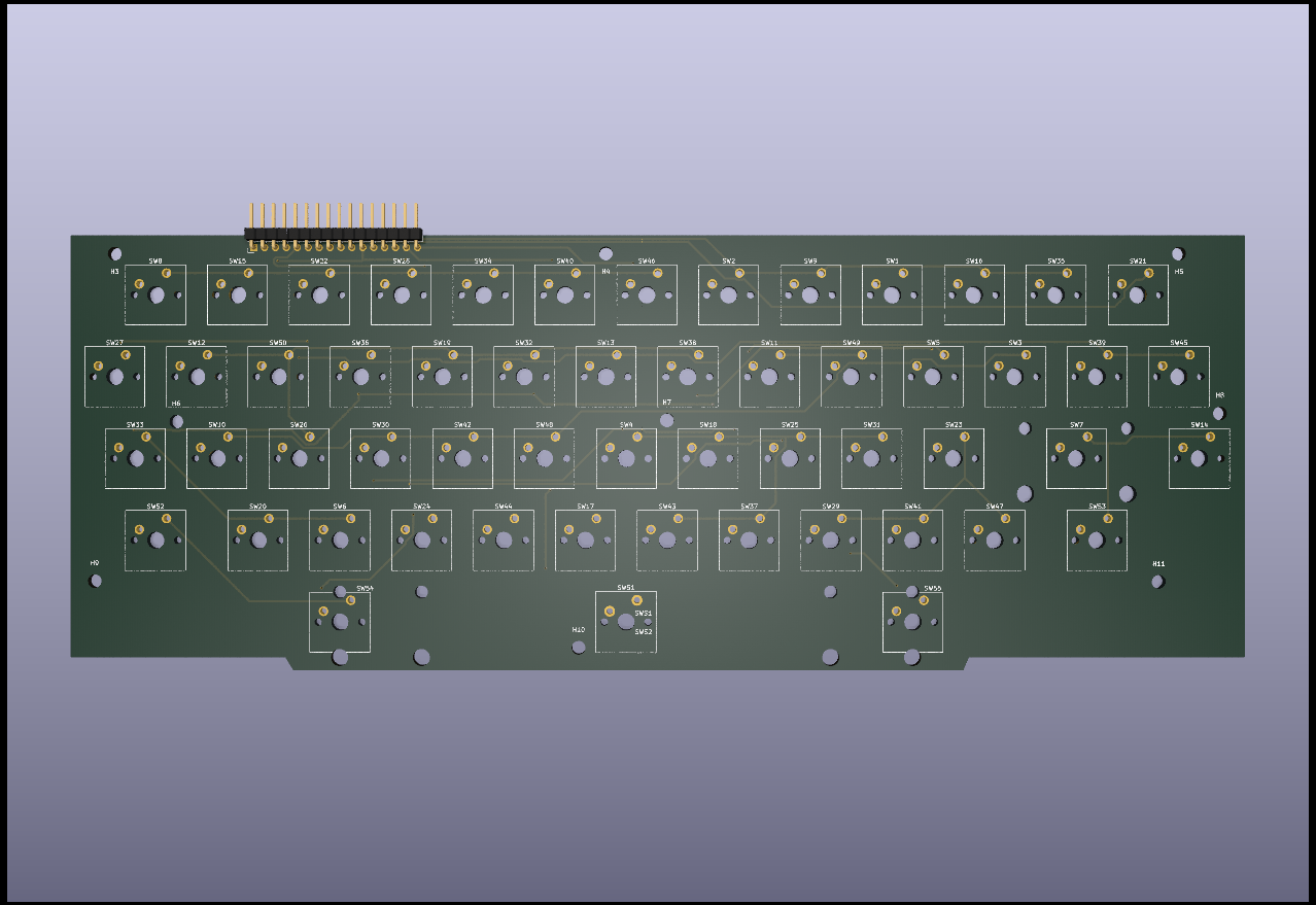
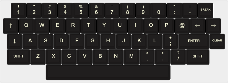
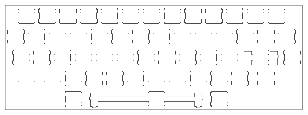
The first draft of the board has been produced for testing
The good bits:
The bad bits:
The keyboard matrix includes a diode alongside each switch to remove ghosting issues. This isn't strictly necessary but if you want to utilise a cheap MCU like the atmega32u4 to convert the keyboard to USB HID, you are going to need those diodes.
If you decide not to use them you will need to bridge the pads for each diode position, this then replicates the original keyboard matrix
The project includes design files for use with the "Keyboard Firmware Builder" website - this generates a binary file to program a microcontroller. The design expects the rows to be wired to the "Bx" pins and the columns to be wired to the "Dx" pins.
The Firmware Builder website can be found here: Keyboard Firmware Builder link
The original keyboard utilises an 8u wide spacebar but these are more just a bit tricky to find in modern fittings, the next best alternative is a 6u wide spacebar which leaves gaps for two more keys, wiring the keyboard to accept extra keys is simple enough and the original matrix has space for four more keys. The original ROMs do not include scanning for those extra unused keys so they won't do anything without modifications to the ROM coding. For emulation purposes it is trivial to map the extra keys to be useful (I suggest using them as modifiers to really expand the range of keypresses or macros that can be operated).
The layout of the keyboard can be quickly prototyped using another online tool called the "Keyboard Layout Editor", you can access it here: Keyboard Layout Editor link
The link includes all of the original design settings but you can also find the settings as a config file in this repository.
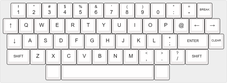
The reproduction boards I've designed have the potential to utilise full 8-bit character set codes (through external character generator roms and additional control lines to the VDG), where this is done it would be necessary to use the modifier keys to access the additional characters in much the same way as the petscii set on vintage Commodore computers.
By using standard MX switches the range of key caps readily available is immense. Brand new ready made sets are cheap enough but keep in mind that the position of some characters on the Dragon keyboard is non-standard (such as brackets appearing on the 8 and 9 keys instead of 9 and 0). You also have a small problem with the break and clear keys as these are not standard (yes there is a "pause break" that comes close).
Most key cap sets are also profiled differently for each row of the keyboard, it isn't a particular problem but some keys are in very different positions - such as the arrow keys so the profile won't look or feel right for those keys compared to others on the same row.
If however you are getting your keycaps fabricated there are options to have the same profile for all of the keys and have the right symbols on each key.
The overall projection height (from pcb to the top of the key) on the original keyboard is nearly 2cm more than you get with modern keys and keycaps. If you put those in a stock case the keys will actually be below the level of the keyboard surround.
Overcoming the difference in height needs the pcb to sit higher, the simplest option (at the moment) is to use two layers of boards. The first sits at the normal height and uses the original mounting points. The second board is mounted to the first using spacers (the pcb design includes holes for M5 sized spacers to be mounted already).
To make the keyboard really robust it should also have a stabilising frame above the PCB, this clips all of the switches together into a single unit, in a similar way to the original hi-tek switches.
| Qty | Value | Footprint | References |
|---|---|---|---|
| 55 | D | Diode_SMD:D_0805_2012Metric | D1, D2, D10, D11, D12, D13, D14, D15, D16, D17, D18, D19, D20, D21, D22, D23 +39 |
| 9 | MountingHole | MountingHole:MountingHole_3.2mm_M3 | H3, H4, H5, H6, H7, H8, H9, H10, H11 |
| 2 | O | Button_Switch_Keyboard:SW_Cherry_MX_1.00u_PCB | SW1, SW49 |
| 2 | Shift | Button_Switch_Keyboard:SW_Cherry_MX_1.50u_PCB | SW52, SW53 |
| 1 | , | Button_Switch_Keyboard:SW_Cherry_MX_1.00u_PCB | SW29 |
| 1 | - | Button_Switch_Keyboard:SW_Cherry_MX_1.00u_PCB | SW35 |
| 1 | . | Button_Switch_Keyboard:SW_Cherry_MX_1.00u_PCB | SW41 |
| 1 | / | Button_Switch_Keyboard:SW_Cherry_MX_1.00u_PCB | SW47 |
| 1 | 1 | Button_Switch_Keyboard:SW_Cherry_MX_1.00u_PCB | SW8 |
| 1 | 2 | Button_Switch_Keyboard:SW_Cherry_MX_1.00u_PCB | SW15 |
| 1 | 3 | Button_Switch_Keyboard:SW_Cherry_MX_1.00u_PCB | SW22 |
| 1 | 4 | Button_Switch_Keyboard:SW_Cherry_MX_1.00u_PCB | SW28 |
| 1 | 5 | Button_Switch_Keyboard:SW_Cherry_MX_1.00u_PCB | SW34 |
| 1 | 6 | Button_Switch_Keyboard:SW_Cherry_MX_1.00u_PCB | SW40 |
| 1 | 6u Switch Stabiliser | Mounting_Keyboard_Stabilizer:Stabilizer_Cherry_MX_6.00u | SWS1 |
| 1 | 7 | Button_Switch_Keyboard:SW_Cherry_MX_1.00u_PCB | SW46 |
| 1 | 8 | Button_Switch_Keyboard:SW_Cherry_MX_1.00u_PCB | SW2 |
| 1 | 8u Switch Stabiliser | Mounting_Keyboard_Stabilizer:Stabilizer_Cherry_MX_8.00u | SWS2 |
| 1 | 9 | Button_Switch_Keyboard:SW_Cherry_MX_1.00u_PCB | SW9 |
| 1 | : | Button_Switch_Keyboard:SW_Cherry_MX_1.00u_PCB | SW16 |
| 1 | ; | Button_Switch_Keyboard:SW_Cherry_MX_1.00u_PCB | SW23 |
| 1 | A | Button_Switch_Keyboard:SW_Cherry_MX_1.00u_PCB | SW10 |
| 1 | At | Button_Switch_Keyboard:SW_Cherry_MX_1.00u_PCB | SW3 |
| 1 | B | Button_Switch_Keyboard:SW_Cherry_MX_1.00u_PCB | SW17 |
| 1 | Break | Button_Switch_Keyboard:SW_Cherry_MX_1.00u_PCB | SW21 |
| 1 | C | Button_Switch_Keyboard:SW_Cherry_MX_1.00u_PCB | SW24 |
| 1 | Clear | Button_Switch_Keyboard:SW_Cherry_MX_1.00u_PCB | SW14 |
| 1 | Ctrl | Button_Switch_Keyboard:SW_Cherry_MX_1.00u_PCB | SW54 |
| 1 | D | Button_Switch_Keyboard:SW_Cherry_MX_1.00u_PCB | SW30 |
| 1 | DRAGON_CONNECTION | Connector_PinHeader_2.54mm:PinHeader_1x16_P2.54mm_Horizontal | J1 |
| 1 | Down | Button_Switch_Keyboard:SW_Cherry_MX_1.00u_PCB | SW33 |
| 1 | E | Button_Switch_Keyboard:SW_Cherry_MX_1.00u_PCB | SW36 |
| 1 | Enter | Button_Switch_Keyboard:SW_Cherry_MX_2.00u_PCB | SW7 |
| 1 | F | Button_Switch_Keyboard:SW_Cherry_MX_1.00u_PCB | SW42 |
| 1 | Fn | Button_Switch_Keyboard:SW_Cherry_MX_1.00u_PCB | SW55 |
| 1 | G | Button_Switch_Keyboard:SW_Cherry_MX_1.00u_PCB | SW48 |
| 1 | H | Button_Switch_Keyboard:SW_Cherry_MX_1.00u_PCB | SW4 |
| 1 | I | Button_Switch_Keyboard:SW_Cherry_MX_1.00u_PCB | SW11 |
| 1 | J | Button_Switch_Keyboard:SW_Cherry_MX_1.00u_PCB | SW18 |
| 1 | K | Button_Switch_Keyboard:SW_Cherry_MX_1.00u_PCB | SW25 |
| 1 | L | Button_Switch_Keyboard:SW_Cherry_MX_1.00u_PCB | SW31 |
| 1 | Left | Button_Switch_Keyboard:SW_Cherry_MX_1.00u_PCB | SW39 |
| 1 | M | Button_Switch_Keyboard:SW_Cherry_MX_1.00u_PCB | SW37 |
| 1 | N | Button_Switch_Keyboard:SW_Cherry_MX_1.00u_PCB | SW43 |
| 1 | P | Button_Switch_Keyboard:SW_Cherry_MX_1.00u_PCB | SW5 |
| 1 | Q | Button_Switch_Keyboard:SW_Cherry_MX_1.00u_PCB | SW12 |
| 1 | R | Button_Switch_Keyboard:SW_Cherry_MX_1.00u_PCB | SW19 |
| 1 | Right | Button_Switch_Keyboard:SW_Cherry_MX_1.00u_PCB | SW45 |
| 1 | S | Button_Switch_Keyboard:SW_Cherry_MX_1.00u_PCB | SW26 |
| 1 | Space | Switch_Keyboard_Cherry_MX:SW_Cherry_MX_PCB_6.00u | SW51 |
| 1 | T | Button_Switch_Keyboard:SW_Cherry_MX_1.00u_PCB | SW32 |
| 1 | U | Button_Switch_Keyboard:SW_Cherry_MX_1.00u_PCB | SW38 |
| 1 | Up | Button_Switch_Keyboard:SW_Cherry_MX_1.00u_PCB | SW27 |
| 1 | V | Button_Switch_Keyboard:SW_Cherry_MX_1.00u_PCB | SW44 |
| 1 | W | Button_Switch_Keyboard:SW_Cherry_MX_1.00u_PCB | SW50 |
| 1 | X | Button_Switch_Keyboard:SW_Cherry_MX_1.00u_PCB | SW6 |
| 1 | Y | Button_Switch_Keyboard:SW_Cherry_MX_1.00u_PCB | SW13 |
| 1 | Z | Button_Switch_Keyboard:SW_Cherry_MX_1.00u_PCB | SW20 |
hackclub/OnBoard
💡 Join 1,000 teenagers and make your first PCB with a $100 grant!

SensorsIot/SuperPower
Here you should find the best power supplies for your low-power projects

TweetyDaBird/Lotus-58-Classic
A split ergo linear keyboard derived from the Lily58 family


tebl/BulkyMIDI-32
A HW build of the MT32-PI project, allowing you to emulate a Roland MT-32 using a Raspberry Pi. Includes enough additional modules to build a MIDI-mountain as well as adapters for connecting to most things retro.

andreili/STM32-PLC
The project is open source and open hardware, the purpose of which is to create a PLC based on STM32 MCU's.

softerhardware/Hermes-Lite
Deprecated project!!! See Hermes-Lite2 at main web site

tmarhguy/alu
8-bit combinational ALU built from scratch with 3,488 CMOS transistors (KiCad + SPICE + Logisim + 1.24M tests
It measures 273.3 × 101.2 mm and has 2 copper layers, 1.6 mm thick.
122 parts. The full list of its parts is on this page, with links to each part's symbol and footprint where PCBKit's library has them.
From the jimbro1000/Dragon3264Keyboard repository on GitHub, at the commit this page was made from: the board is keyboardTest.kicad_pcb and its schematic keyboardTest.kicad_sch. PCBKit opens the board in the browser, with nothing to install.
Its repository publishes it under the MIT licence: you may reuse it on that licence's terms (keep the author's notice, and for a copyleft licence share your changes alike).