

4 layers98 × 130 mm

 jimbro1000/ACSI2STremix
Remix of the original compact ACSI2STM to make it easier to fit and assemble
ACSI2ST is an open-source printed circuit board by jimbro1000, from the jimbro1000/ACSI2STremix repository on GitHub, published under the GPL-3.0 licence. It is a 2-layer board of 49.5 × 64.7 mm with 50 parts on 59 nets, routed with 556 tracks and 100 vias.
It is built around the STM32F103C8T6 and CR2032. Its parts include 17 capacitors, 11 resistors, 8 connectors, 2 ICs and 2 diodes. It belongs with the STM32 boards of this library.
This project is based on the ACSI2STM project by Jean-Matthieu Coulon (retro16). https://github.com/retro16/acsi2stm
The schematics for the project are unchanged from the original (ignoring the addition of an additional 5V connection).
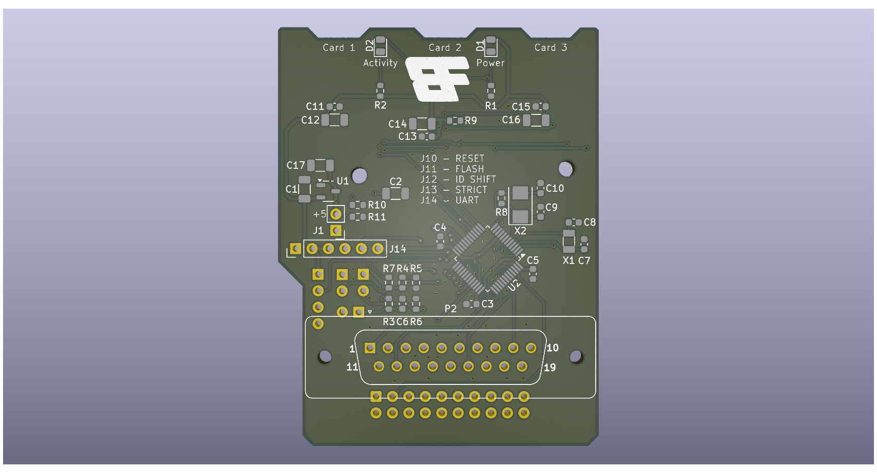
The changes are primarily to the PCB layout. Bulky components have been moved to the rear of the board to permit extra clearance against the ST case.
Where feasible the board dimensions have been reduced.
All 0402 SMT components have been swapped for 0603 parts to ease the job of hand soldering. For the same reason the clearance between parts has been increased.
The DB19 footprint has been reimplemented to correctly align the pins and to use individual 1mm diameter board pins (such as these: https://www.aliexpress.com/item/4001366384308.html). This requires careful alignment of the pins during assembly - I strongly recommend using a spare, unpopulated PCB as a jig.
The USB power connection has been moved from the right, to the left (as viewed from the computer) to bring the connection closer to the cartridge port for those using a SidecarT.
The build of the board should now be easier and there is no particular build sequence needed if you are hand soldering the board. It is probably worth leaving the DB19 pins until last though to avoid bending them.
The firmware for programming the STM microcontroller should be taken from the original acsi2stm github repository, no changes should be required as of version 5.0d (November 2024). All of the documentation in that repository should be applicable here too.
Thanks to
| Qty | Value | Footprint | References |
|---|---|---|---|
| 7 | 100nF | Capacitor_SMD:C_0603_1608Metric | C3, C4, C5, C6, C11, C13, C15 |
| 6 | 100uF | Capacitor_SMD:C_1206_3216Metric | C1, C2, C12, C14, C16, C17 |
| 5 | 1K | Resistor_SMD:R_0603_1608Metric | R1, R2, R4, R5, R7 |
| 4 | 22pF | Capacitor_SMD:C_0603_1608Metric | C7, C8, C9, C10 |
| 3 | 100K | Resistor_SMD:R_0603_1608Metric | R3, R6, R9 |
| 3 | Micro_SD_Card_Det2 | Connector_Card:microSD_HC_Hirose_DM3BT-DSF-PEJS | CARD1, CARD2, CARD3 |
| 2 | 5.1K | Resistor_SMD:R_0603_1608Metric | R10, R11 |
| 2 | LED_Filled | LED_SMD:LED_0805_2012Metric | D1, D2 |
| 2 | MountingHole | MountingHole:MountingHole_2.5mm | H1, H2 |
| 1 | 1M | Resistor_SMD:R_0603_1608Metric | R8 |
| 1 | 32.768KHz | Crystal:Crystal_SMD_3215-2Pin_3.2x1.5mm | X1 |
| 1 | 5V PWR | Connector_PinHeader_2.54mm:PinHeader_1x02_P2.54mm_Vertical | J1 |
| 1 | 8MHz | Crystal:Crystal_SMD_5032-2Pin_5.0x3.2mm | X2 |
| 1 | CR2032 | Battery:BatteryHolder_Keystone_1060_1x2032 | BT1 |
| 1 | DB-19 Male | ACSI2ST:DSUB-19_Pins_Vertical | P2 |
| 1 | FLASH | Connector_PinHeader_2.54mm:PinHeader_1x02_P2.54mm_Vertical | J11 |
| 1 | IDC20 | Connector_IDC:IDC-Header_2x10_P2.54mm_Vertical | P1 |
| 1 | ID_SHIFT | Connector_PinHeader_2.54mm:PinHeader_1x04_P2.54mm_Vertical | J12 |
| 1 | LOGO | PowerBoard:BoardFolk | Ge |
| 1 | RESET | Connector_PinHeader_2.54mm:PinHeader_1x02_P2.54mm_Vertical | J10 |
| 1 | STM32F103C8T6 | Package_QFP:LQFP-48_7x7mm_P0.5mm | U2 |
| 1 | STRICT | Connector_PinHeader_2.54mm:PinHeader_1x02_P2.54mm_Vertical | J13 |
| 1 | UART | Connector_PinHeader_2.54mm:PinHeader_1x06_P2.54mm_Vertical | J14 |
| 1 | USB_C_PowerOnly | Connector_USB:USB_C_Receptacle_GCT_USB4135-GF-A_6P_TopMnt_Horizontal | USB1 |
| 1 | XC6206PxxxMR | Package_TO_SOT_SMD:SOT-23-3 | U1 |


pekkaroi/bldc-drive
Cheap and simple brushless DC motor driver designed for CNC applications using STM32 microcontroller

hardenedlinux/cheap-pcb
Cheap PCB: Better understanding the current status of hardware supply chain

NYDEREK/LineFollower_GRUZIK2.0-light
GRUZIK2.0 is simple light construction made for "line follower light" competition
It measures 49.5 × 64.7 mm and has 2 copper layers, 1.6 mm thick.
50 parts, built around the STM32F103C8T6 and CR2032. The full list of its parts is on this page, with links to each part's symbol and footprint where PCBKit's library has them.
From the jimbro1000/ACSI2STremix repository on GitHub, at the commit this page was made from: the board is ACSI2ST.kicad_pcb and its schematic ACSI2ST.kicad_sch. PCBKit opens the board in the browser, with nothing to install.
Its repository publishes it under the GPL-3.0 licence: you may reuse it on that licence's terms (keep the author's notice, and for a copyleft licence share your changes alike).