DRAGON 32 CPU Issue 2
This project is a recreation of the SA2120 CPU Mainboard
for the 1982 Dragon Data Dragon 32
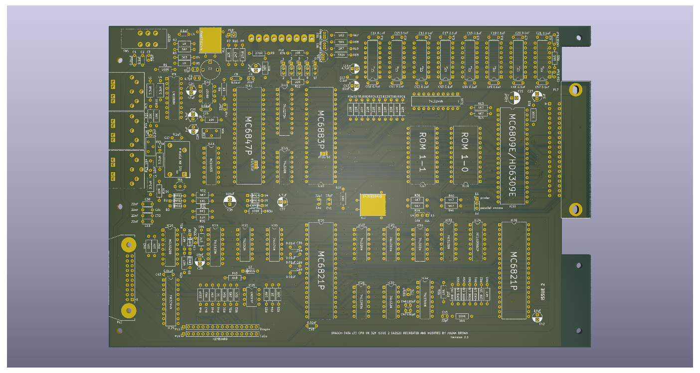
Everything (excluding modifications) is taken from the SA2120
schematics. Component positioning is as close to the original
too. The DRAM positions are as close as possible to the 1982
board but in preference use 4164s instead and set the
memory configuration jumpers appropriately, this avoids
transplanting a riser board to use the 16x16k configuration.
The 16x16k should still work of course...
The two ROMS will need to be sourced from original boards or an
adapter used to allow the use of modern, available EPROM or EEPROM
components
The variable resistor (RV1) and motor relay (RL1) are adjusted
for modern, available components. The cartridge port is based
on a modern design but may still be hard to source
Important - Read This Bit!
September 2023: In the year since I started developing this board the
availability of the MC6883P/74LS783N SAM chip has gone from "easy to
find" to almost unobtainable. The only known and proven source is from
DragonPlus Electronics. Please make sure you can find one before starting
your build
There is work being done to create a replacement for the SAM chip
but this is yet to become available
The rarer (but ironically easier to buy) 74LS785 should work as
a substitute
Caveat
The scans on the original SA2120 schematics are not always clear
and it has taken a fair amount of careful study to get everything
correct but there is no guarantee at this time that the board
design is as intended
The values of passive components are taken from observation of
an original production board, in most cases those values do
match the schematics, but not always
Revision 2.3 of this board is in a genuinely usable state but
still with caveats
Working
In the current state (2.3) basic operation is tested working on
CPU, RAM, Keyboard, Joystick and Video.
Working with caveat
Audio appears to be good but not fully tested (given the joysticks
work and the board produces audio there isn't much to go wrong
here)
Untested
Parallel port is untested in either mode beyond verifying signals
to the port are present
Modifications
Joysticks
The two joystick ports provide a second fire button capability
wired to consecutive keyboard rows, as per the Tandy CoCo.
Unless a two button joystick is used this make no difference to
the operation of the computer. It also requires the use of 6-pin
DIN sockets, these are pin compatible with the 5-pin originals
so a regular single button joystick can still be used.
The two extra buttons can also be disabled by omitting L3 and L4
Parallel Port
An extra jumper has been introduced to bypass the logic inverter
on the STROBE line. When bypassed the parallel port should
operate as a communication port for DRIVEWIRE. In effect this
enables the printer port to behave as a TTL serial connection.
Speed is limited by software and raw clock speed.
Memory Addressing
The board is configurable between 32k and 64k ram addressing
using jumper 13/14. Position 13 is for original 32k ram
configuration, position 14 is for an upgraded 64k ram. Note
that this then requires removal of some additional passive
components and assumes that suitable 64k x 1 ram chips are
fitted in IC1 to IC8.
Jumper 9/10 has been added for consistency with some of the
other early designs and for compatibility with the 64k
upgrade. It is important to avoid populating C50-57 when
using this option, along with C12, C58, C59 and R66.
See [World of Dragon: Dragon 32 - 64k Upgrade]
(http://archive.worldofdragon.org/index.php?title=Dragon_32_-_64K_Upgrade)
Video
The Rev 2.1 board adds two (hidden) solder jumpers for adapting
the board to NTSC output. By default these have a bridge putting
the board in PAL mode so unless you want NTSC output there is
nothing to be done.
To change the configuration the bridge on both jumpers needs to be
cut and the option pads bridged with solder. This bypasses the
additional logic for video sync. The jumpers are JP15/16 and
JP17/18, these are positioned below IC15 and IC12 respectively.
The default position is marked.
To complete the change an NTSC adapter board needs to be fitted.
This piggybacks the 6847 position and adds in a suitable NTSC
video modulator. The output of the NTSC board goes to PL8, next
to the PAL colour crystal XL1.
In this configuration there is no need to fit a number of components:
- IC9
- IC10
- IC11
- IC14
- IC21
- IC22
- IC26
- IC27
- IC29
- IC30
- IC32
- C2
- C3
- C5
- C6
- C7
- C24
- C25
- C28
- C46
- C47
- C71
- R2
- R3
- R4
- R17
- R18
- R33
- R34
- R35
- R44
- XL1
Substitutions
Many of the original components are simply unobtainable or
just very hard (and expensive) to locate. The transistors
will need modern substitutes as the BC141, BC212 and 2N2369
are all obsolete but thankfully these are fairly run-of-the-mill
transistors and shouldn't cause any particular issues
The video op-amp SFC2318D at position IC10 is especially
hard to find and this one component can easily double the
price of populating the board if an original is used...
I've identified a Harris HA-5111 as a likely candidate, it
is an audio op-amp rated for upto 40MHz so plenty of
bandwitdh for a simple PAL/NTSC video signal. There are of
course lots of other single channel op-amps out there in a
dip-8 format but they tend to be expensive (as in really
expensive) possibly cheaper than a real 2318D but not by
much, some are stupidly expensive (nearly 100x that
2318D). The HA-5111 should be about £0.90
The CPU, PIAs and VDG are all fairly easy to obtain online
and possibly even new (MC6821s are still made and there
are lots of compatible alternatives). A and B rated components
should all be usable but make sure the processor is an "09e".
The Hitachi HD6309 is usable but may cause crashes in some
software due to lazy coding
The 4000 series logic chips are particularly tricky - some
have modern equivalents. The MC14053 and MC14050 can be
replaced with modern CD4000 series chips. The MC14529
was replaced with a CD4000 series logic chip but even that
is now obsolete with no valid replacement
The LM1889 is another hard to find chip but still reasonably
cheap online when found
The SAM and the two ROMs are genuinely unavailable except
from donor boards but the ROMs can be replaced with 27C64
eproms fitted with a suitable conversion shim board.
The Future
As these parts become harder to find it is inevitable that
replacements and redesigns will be needed. Abandoning the
original composite video output circuits and moving to a
(more) modern RGB or VGA output instead removes a big
chunk of the more troublesome hardware, notably the LM1889
and SFC2318 along with a number of other common logic chips.
If a composite output is still required an ADR724J can be
used to generate the necessary signal, all in one chip
A cheat replacement for the 6847 exists, using a raspberry
pi pico but this could easily be reduced even further an
FPGA (assuming such chips are readily available again)
The ROMs can be replaced with a single EPROM/EEPROM, even
opening up the option of switchable ROM images given the
size of a modern EPROM's addressable memory. I have a
mini conversion board that fits into a single socket with
a jumper to the E pin of the second socket. (see
https://github.com/jimbro1000/Dragon32RomFix)
The one thing that isn't so quickly removed from the
equation is that MC14529 - a dual 4-channel data
selector. Onsemi and Harris used to made the CD4529
that replaced the original MC14529 and it is only fairly
recently that the chip became obsolete so there is
stock out there but the chip is somewhat specialised and
as such really isnt easily substituted even with a modern
SMD package.
The most likely candidate here is to use a GAL chip to
simulate the switching behaviour of the MC14529 combined
with discrete analogue switches (such as 74LVC1G3157). This
will necessitate a new board design or a plugin board to
match the pinout of the 4529 chip


