
4 layers100 × 100 mm

 jhugon/kicad_transient_load
For step-response testing power supplies
Kicad transient load is an open-source printed circuit board by jhugon, from the jhugon/kicad_transient_load repository on GitHub. It is a 2-layer board of 35 × 50 mm with 11 parts on 7 nets, routed with 18 tracks and 0 vias.
It is built around the ZVN4306A. Its parts include 4 resistors, 3 connectors and 1 transistor.
For step-response testing power supplies.
A resistor and MOSFET switch hooked up to a BNC jack. Hook up a signal generator to the BNC jack and the other leads to the power supply device under test.
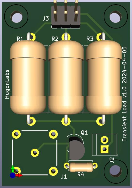
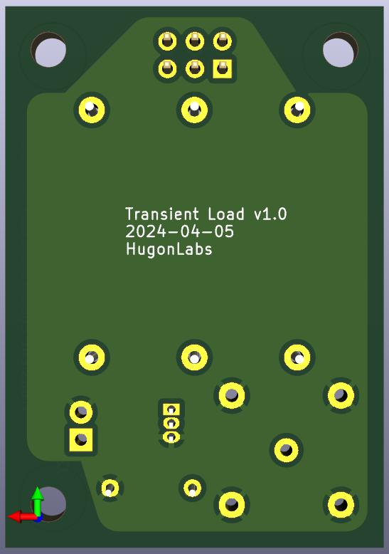
| Qty | Value | Footprint | References |
|---|---|---|---|
| 3 | R_US | Resistor_THT:R_Axial_DIN0918_L18.0mm_D9.0mm_P22.86mm_Horizontal | R1, R2, R3 |
| 1 | 10K | Resistor_THT:R_Axial_DIN0207_L6.3mm_D2.5mm_P7.62mm_Horizontal | R4 |
| 1 | BNC In | AAAA_Project_Library:BNC_TE-Connectivity_1-1337445-0 | J1 |
| 1 | Conn_02x03_Odd_Even | Connector_PinHeader_2.54mm:PinHeader_2x03_P2.54mm_Vertical | J3 |
| 1 | Screw_Terminal_01x02 | TerminalBlock_TE-Connectivity:TerminalBlock_TE_282834-2_1x02_P2.54mm_Horizontal | J2 |
| 1 | ZVN4306A | Package_TO_SOT_THT:TO-92_Inline | Q1 |
The 8 most common of 11 parts.

google/mozc-devices
Circuit diagrams and firmware source code for Gboard DIY keyboards


FrameworkComputer/ExpansionCards
Reference designs and documentation to create Expansion Cards for the Framework Laptop

hoglet67/RGBtoHDMI
Bare-metal Raspberry Pi project that provides pixel-perfect sampling of Retro Computer RGB/YUV video and conversion to HDMI

hackclub/OnBoard
💡 Join 1,000 teenagers and make your first PCB with a $100 grant!


tardate/LittleArduinoProjects
a collection of "Little Electronic & Arduino Projects", most involving electronics or an Arduino in one way or another!
It measures 35 × 50 mm and has 2 copper layers, 1.6 mm thick.
11 parts, built around the ZVN4306A. The full list of its parts is on this page, with links to each part's symbol and footprint where PCBKit's library has them.
From the jhugon/kicad_transient_load repository on GitHub, at the commit this page was made from: the board is kicad_transient_load.kicad_pcb and its schematic kicad_transient_load.kicad_sch. PCBKit opens the board in the browser, with nothing to install.
Its repository states no licence, so its author keeps all rights: ask jhugon before reusing the design.