2 layers98 × 27 mm

 jgOhYeah/FarmBaseStation
Base station for connecting remote sensors to Thingsboard.
POE BaseStation is an open-source printed circuit board by jgOhYeah, from the jgOhYeah/FarmBaseStation repository on GitHub. It is a 2-layer board with 5 parts on 21 nets, routed with 31 tracks and 18 vias.
Its parts include 2 connectors, 1 resistor, 1 IC and 1 diode. It belongs with the sensors and measurement boards and the ESP32 and RISC-V boards of this library.
Remote sensors use PJON over LoRa radio to communicate. The Thingsboard Gateway MQTT API is used to connect on the Thingsboard side.
See here for other sensors and more information on the system.
Written by Jotham Gates August 2023
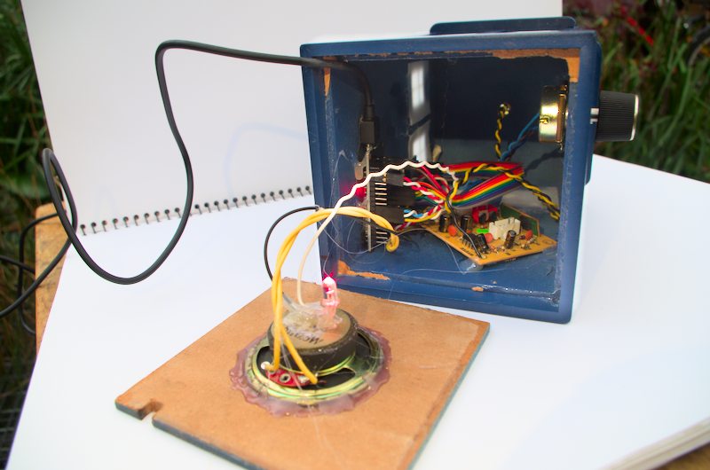
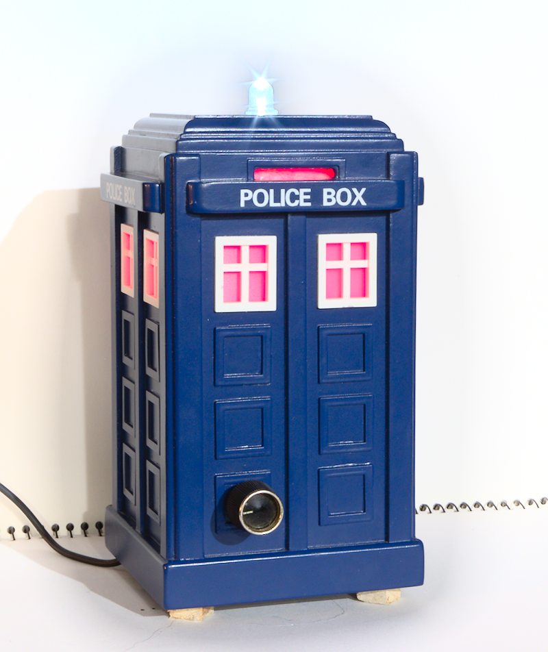
The Github repository containing all design files and code is here.
BaseStationCode directory.BaseStationCode/credentials.example.ini and name this credentials.ini. Fill out the settings in this file for the WiFi network to connect to, MQTT broker, Thingsboard credentials and Over The Air (OTA) update settings.Over the air (OTA) updates can be used to update the software on the base station once it has been programmed for the first time. To do this:
credentials.ini to match those currently set on the device.Tardis-OTA from its default Tardis environment (likewise for the TVAnt environemnt for ethernet).The base station uses an ESP32 development board as its base. An SX1278 LoRa radio module breakout board is connected via jumper leads. LEDs are soldered along with their respective current limiting resistors to wires that can be plugged into the ESP32 board. An audio amplifier and speaker can also be connected for alarm functionality. I salvaged this from the sound effects module of a broken children's ride on toy car.

I originally planned to use the build in DAC of the ESP32 to play sounds on alarm conditions. At this point I haven't succeded in this (currently using the TunePlayer library to play simple monotonic songs instead). I did come across the ESP32-A2DP library that allows the use of this unit as a terrible sounding bluetooth speaker.
This sketch is the bt_music_receiver_to_internal_dac example from the ESP32-A2DP library with the addition of flashing lights.
| Qty | Value | Footprint | References |
|---|---|---|---|
| 1 | 220 | Resistor_THT:R_Axial_DIN0207_L6.3mm_D2.5mm_P15.24mm_Horizontal | R1 |
| 1 | Conn_01x10_Socket | Connector_PinSocket_2.54mm:PinSocket_1x10_P2.54mm_Vertical | J2 |
| 1 | LED | LED_THT:LED_D3.0mm | D1 |
| 1 | Olimex ESP32-POE | Connector_PinSocket_2.54mm:PinSocket_1x10_P2.54mm_Vertical | J1 |
| 1 | Ra01_Breakout_Module-Ra01_Breakout_Module | Package_DIP:DIP-8_W7.62mm_Socket_LongPads | U1 |
5 parts. The full list of its parts is on this page, with links to each part's symbol and footprint where PCBKit's library has them.
From the jgOhYeah/FarmBaseStation repository on GitHub, at the commit this page was made from: the board is BaseStationSchematics/POE_BaseStation/POE_BaseStation.kicad_pcb and its schematic BaseStationSchematics/POE_BaseStation/POE_BaseStation.kicad_sch. PCBKit opens the board in the browser, with nothing to install.
Its repository states no licence, so its author keeps all rights: ask jgOhYeah before reusing the design.

joypad-ai/joypad-os
Universal controller firmware for building adapters, dongles, and custom controllers.

OLIMEX/OLINUXINO
OLINUXINO is Open Source / Open Hardware, low cost from EUR 24 Linux Industrial grade Single Board Computer capable to operate -25+85C

jamro/tiny-engineer
A small desktop robot that brings an AI coding assistant to life, physically acting out when it reads files, thinks, writes code, and finishes work.

hackclub/OnBoard
💡 Join 1,000 teenagers and make your first PCB with a $100 grant!


Luos-io/luos_engine
Open-source and real-time orchestrator for cyber-physical-systems, to easily design, test and deploy embedded applications and digital twins.