2 layers37 × 19 mm
Passive rpi hub75-adapter
hzeller/rpi-rgb-led-matrix
Controlling up to three chains of 64x64, 32x32, 16x32 or similar RGB LED displays using Raspberry Pi GPIO
2 parts4.4kGPL-2.0

 jf-lab/chendoscope6
Compact Head-mounted Endoscope for calcium imaging in mice.
Camera interface board is an open-source printed circuit board by jf-lab, from the jf-lab/chendoscope repository on GitHub. It is a 2-layer board of 6.2 × 8 mm with 2 parts on 15 nets, routed with 33 tracks and 5 vias.
It belongs with the interfaces and adapters boards of this library.
Complete instructions on how to use the CHEndoscope, including assembly, surgery, behavioural protocols and data analysis can be in the CHEndoscope protocols paper.
Analysis of calcium imaging videos uses CHEndoscope-minipipe
The CHEndoscope consists of 4 plastic components that can be 3D printed
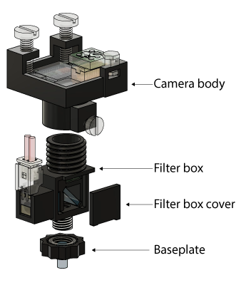
When printing these parts, we recommend a print resolution of at most 100μm (50μm works best in our hands). Our lab has experimented with various FDM, SLA and material jetting printers, and find that SLA printers such as the Formlabs Form2 render best results. FDM printers often lack the resolution required to render the fine threads and internal details of several CHEndoscope parts. In addition to print resolution, make sure the material you are printing with does not fluoresce or otherwise interfere with the imaging path when exposed to 470nm or 535nm light.
Download CHEndoscope STL files for 3D printing, or STEP files if you want to modify the base CHEndoscope design.
In order to capture images from the CHEndoscope, you will need to install acquisition software that interfaces with the CHEndoscope's Ximea USB camera. This code is compatible with Linux and Windows systems.
Open a new cmd window
cd [path for storing video files]python "path\to\vid.py"To change gains/exposure etc:
ncat -u 127.0.0.1 6557[set_gain 10]| Qty | Value | Footprint | References |
|---|---|---|---|
| 1 | CONN_01X05 | footprints:SMD_05_Hole | P1002 |
| 1 | MU9P_MH_CONN_M | footprints:DF12A-20DS-M | P1001 |
It measures 6.2 × 8 mm and has 2 copper layers, 1.6 mm thick.
2 parts. The full list of its parts is on this page, with links to each part's symbol and footprint where PCBKit's library has them.
From the jf-lab/chendoscope repository on GitHub, at the commit this page was made from: the board is camera-interface-board-PCB/camera-interface-board.kicad_pcb. PCBKit opens the board in the browser, with nothing to install.
Its repository states no licence, so its author keeps all rights: ask jf-lab before reusing the design.
hzeller/rpi-rgb-led-matrix
Controlling up to three chains of 64x64, 32x32, 16x32 or similar RGB LED displays using Raspberry Pi GPIO


adamws/kicad-kbplacer
KiCad plugin for automatic keyboard's key placement and routing

Luos-io/luos_engine
Open-source and real-time orchestrator for cyber-physical-systems, to easily design, test and deploy embedded applications and digital twins.

NVNTLabs/switch2-SDEX2M2
Micro SD Express to M.2 NVME Adapter for Nintendo Switch 2

BlueSCSI/BlueSCSI-v2
BlueSCSI v2/Ultra - an open source, open hardware, SCSI emulator using the Pi Pico PR2040 and Pico 2 RP2350

ohmtech-rdi/eurorack-blocks
Software to Hardware Prototyping for Eurorack using C++, Max/Gen~ or Faust
