

2 layers200 × 100 mm
Polykit x voice card
polykit/polykit-x-voice-card
Schematics and PCB layout for a voice card with multimode filter for a polyphonic synthesizer
207 parts58

 jes/autopatzer30
Automatic chess board
Autopatzer is an open-source printed circuit board by jes, from the jes/autopatzer repository on GitHub. It is a 2-layer board of 124.5 × 77.5 mm with 40 parts on 117 nets, routed with 800 tracks and 52 vias.
It is built around the CD4051BE and IRF540N. Its parts include 16 connectors, 9 ICs, 7 resistors, 1 diode and 1 transistor. It belongs with the NXP (LPC, Kinetis, i.MX RT) boards of this library.
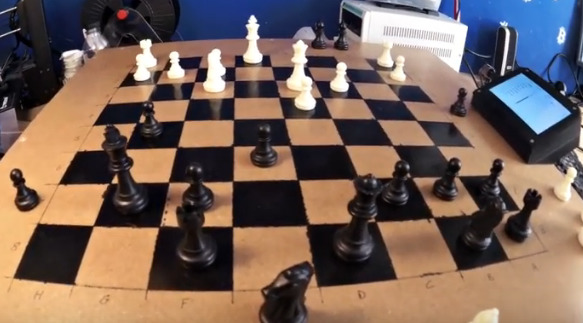
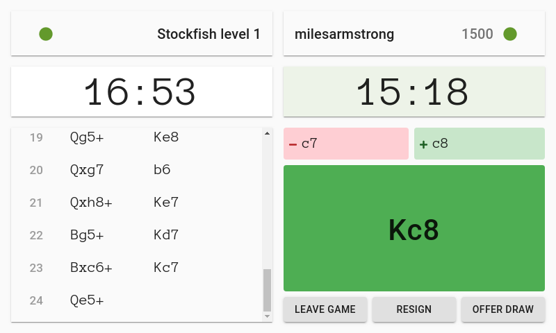
An automatic chess board, supporting online play with people all over the world via the Lichess Boards API.
This repo contains FreeCAD files for the mechanical design, KiCad files for PCB design, Arduino code to run on the microcontroller, Perl code for the library/program that interfaces with the controller, and JavaScript code for the user interface and Lichess interface.
You can watch a video of the board if you want.
I thoroughly encourage you to build an Autopatzer board. You'll need:
There aren't currently a decent set of instructions, so if you want to build one let's try and write some instructions as you go so that it might be easier for whoever comes next!
There are some notes about how you might want to change the design in my blog post: https://incoherency.co.uk/blog/stories/autopatzer.html
There is a NEMA17 stepper motor for each of the X and Y axis, from an old 3d printer. The stepper motors are controlled by A4988 stepper motor drivers, which are controlled using the step/direction pins, driven by the AccelStepper Arduino library. The electromagnet is switched on and off with a MOSFET. The pieces are detected with an analogue hall effect sensor under each square. These 64 analogue signals are reduced to 8 signals with 8x CD4051 8-to-1 analogue multiplexers. All of the code for this runs on a Teensy 3.2 microcontroller, and the rest is adequately explained by this diagram:
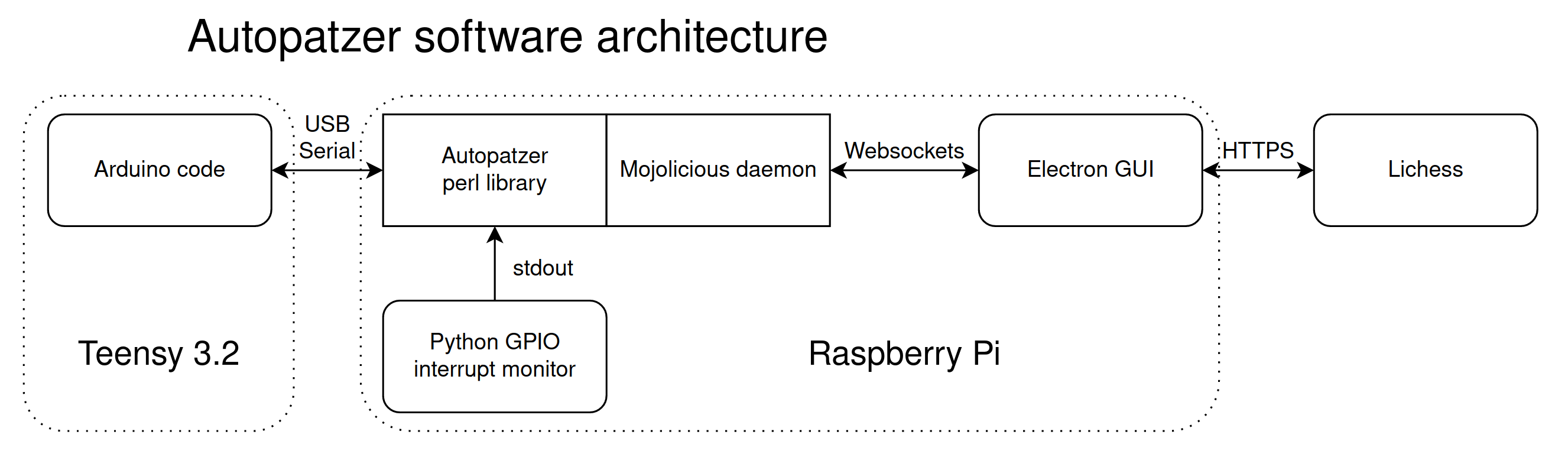
The Electron app providing the user interface is by Miles Armstrong: miles@milesarmstrong.co.uk
The rest is by James Stanley: james@incoherency.co.uk
| Qty | Value | Footprint | References |
|---|---|---|---|
| 8 | CD4051B | Package_DIP:DIP-16_W7.62mm | U2, U3, U4, U5, U6, U7, U8, U9 |
| 8 | Conn_01x08_Male | Connector_PinHeader_2.54mm:PinHeader_1x08_P2.54mm_Vertical | J1, J2, J3, J4, J5, J6, J7, J8 |
| 7 | R | Resistor_THT:R_Axial_DIN0411_L9.9mm_D3.6mm_P12.70mm_Horizontal | R1, R2, R3, R4, R5, R6, R7 |
| 4 | Conn_01x02_Male | Connector_PinHeader_2.54mm:PinHeader_1x02_P2.54mm_Vertical | J10, J14, J15, J16 |
| 2 | Conn_01x04_Male | Connector_PinHeader_2.54mm:PinHeader_1x04_P2.54mm_Vertical | J9, J13 |
| 2 | Conn_02x03_Odd_Even | Connector_PinHeader_2.54mm:PinHeader_2x03_P2.54mm_Vertical | J11, J12 |
| 2 | Pololu_Breakout_A4988 | Module:Pololu_Breakout-16_15.2x20.3mm | A1, A2 |
| 1 | D | Diode_THT:D_5W_P12.70mm_Horizontal | D1 |
| 1 | IRF540N | Package_TO_SOT_THT:TO-220-3_Vertical | Q1 |
| 1 | Teensy3.2 | autopatzer:Teensy30_31_32_LC | U1 |
The 36 most common of 40 parts.
It measures 124.5 × 77.5 mm and has 2 copper layers, 1.6 mm thick.
40 parts, built around the CD4051BE and IRF540N. The full list of its parts is on this page, with links to each part's symbol and footprint where PCBKit's library has them.
From the jes/autopatzer repository on GitHub, at the commit this page was made from: the board is kicad/autopatzer/autopatzer.kicad_pcb. PCBKit opens the board in the browser, with nothing to install.
Its repository states no licence, so its author keeps all rights: ask jes before reusing the design.
polykit/polykit-x-voice-card
Schematics and PCB layout for a voice card with multimode filter for a polyphonic synthesizer

polykit/polykit-x-mainboard
Schematics and PCB layout for a mainboard for an 8 voice polyphonic synthesizer


GlobalSequence/quadulator
Quadulator - A quad LFO/ADSR envelope generator for Eurorack synthesizers

ezcGman/tiny-power-meter
A very tiny 3-phase power meter to measure your homes power consumption and report to Home Assistant!


Oblique-Industry/Oblique-Easel
Code, Electronics, and Industrial Design for the Oblique Easel Artmaschine Cyberdeck