2 layers102 × 85 mm
Superflat
hackclub/OnBoard
💡 Join 1,000 teenagers and make your first PCB with a $100 grant!
94 parts915
 jemtech/ILDA49
A 16bit 6ch DAC for ILDA up to 400kpps
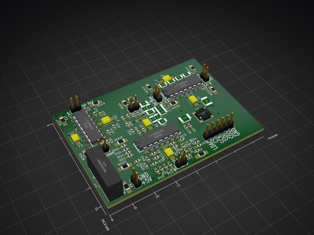
Ildagenerator is an open-source printed circuit board by jemtech, from the jemtech/ILDA repository on GitHub. It is a 2-layer board of 75.9 × 54.2 mm with 94 parts on 79 nets, routed with 397 tracks and 10 vias.
It is built around the NMA0509SC, LT1356CN and LTC2656BIFE-L16#PBF. Its parts include 60 resistors, 8 connectors, 6 fuses, 5 ICs and 2 capacitors.


This project is a DAC (digital to analog converter) which generates six differential signals based on the ILDA (International Laser Display Association) ISP-DB25 standard. Two signals for the X and Y axis (-10V to +10V), four signals for the channels red, green and blue and one custom colour (0V to +5V). The DAC is controlled via SPI. In this case the software is written for a "Raspberry Pi", but any other controller can be used.
This project contains two sections:
The hardware is designed with KiCad. "ILDA/hardware/kicad/" Using 5 channels (x,y,r,g,b) with 16bit at 50MHz SPI speed the DAC reaches theoretically 400kpps (50000KHz ÷ (5×24bit) = 416kpps).
Now you can run the software with "sudo ./ildaNode".
| Qty | Value | Footprint | References |
|---|---|---|---|
| 48 | 10kΩ | Resistors_SMD:R_0603_HandSoldering | R1, R2, R3, R10, R11, R12, R13, R14, R15, R16, R19, R20, R23, R24, R27, R28 +32 |
| 13 | 5.6V | Resistors_SMD:R_1206_HandSoldering | MOV1, MOV2, MOV3, MOV4, MOV5, MOV6, MOV7, MOV8, MOV9, MOV10, MOV11, MOV12, MOV13 |
| 12 | 470Ω | Resistors_SMD:R_0603_HandSoldering | R17, R18, R21, R22, R25, R26, R29, R30, R57, R58, R59, R60 |
| 6 | 1µ | Capacitors_Tantalum_SMD:TantalC_SizeB_EIA-3528_HandSoldering | F1, F2, F3, F4, F5, F6 |
| 3 | LT1356CN | DIP-14__300 | U2, U3, U4 |
| 2 | 0.1µF | Capacitors_SMD:C_0805_HandSoldering | C1, C2 |
| 1 | CONN_4 | Pin_Headers:Pin_Header_Straight_1x02 | P8 |
| 1 | CONN_6 | Pin_Headers:Pin_Header_Straight_1x06 | P7 |
| 1 | LTC2656BIFE-L16 | custom:TSSOP-20_4.4x6.5mm_Pitch0.65mm_21GND | U1 |
| 1 | NMA0509SC | footprints:NMA_5V_12V_15V_Series | U5 |
| 1 | Out Blue | SIL-2 | P5 |
| 1 | Out C1 | SIL-2 | P6 |
| 1 | Out Green | SIL-2 | P4 |
| 1 | Out Red | SIL-2 | P3 |
| 1 | Out X | SIL-2 | P1 |
| 1 | Out Y | SIL-2 | P2 |
It measures 75.9 × 54.2 mm and has 2 copper layers, 1.6 mm thick.
94 parts, built around the NMA0509SC, LT1356CN and LTC2656BIFE-L16#PBF. The full list of its parts is on this page, with links to each part's symbol and footprint where PCBKit's library has them.
From the jemtech/ILDA repository on GitHub, at the commit this page was made from: the board is hardware/kicad/ildagenerator.kicad_pcb. PCBKit opens the board in the browser, with nothing to install.
Its repository states no licence, so its author keeps all rights: ask jemtech before reusing the design.
hackclub/OnBoard
💡 Join 1,000 teenagers and make your first PCB with a $100 grant!

eddyem/stm32samples
Code samples and ready projects based on bare-metal STM32


apuder/TRS-IO
TRS-IO gives a TRS-80 Model 1/III online capabilities and provides access to a variety of services. TRS-IO currently features the following capabilities:

