

4 layers100 × 100 mm
DMXion 4port node
NEOgHacking/DMXion_4Port_Node
A 4 port dmx node with rdm funtionallity. Connects via ARTNET or sACN
275 parts2GPL-3.0

 jeffqchen/Philips-CDi-450-Power-Adapter9
Philips CD-i 450 Power Adapter
Philips CDi-450-Power Adapter is an open-source printed circuit board by jeffqchen, from the jeffqchen/Philips-CDi-450-Power-Adapter repository on GitHub, published under the CC-BY-SA-4.0 licence. It is a 2-layer board of 40.2 × 31.2 mm with 14 parts on 12 nets, routed with 48 tracks and 2 vias.
It is built around the 1N4148W and RJ45. Its parts include 5 diodes, 4 resistors and 3 connectors. It belongs with the interfaces and adapters boards of this library.
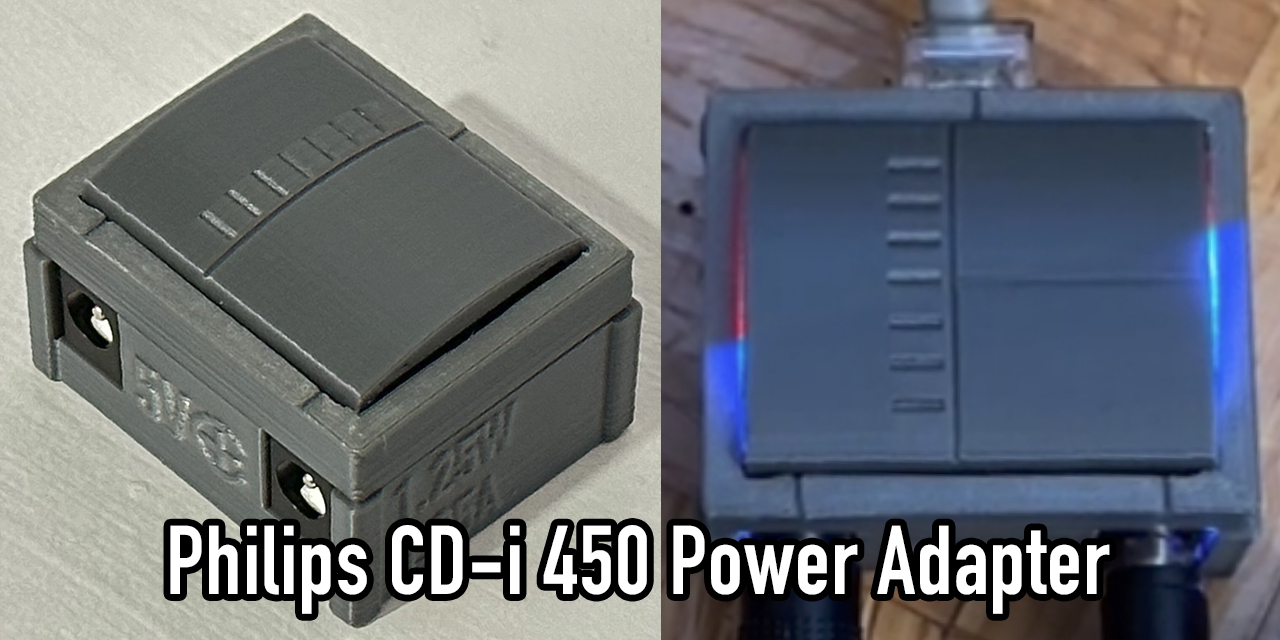
Zaxour designed a new replacement power supply that takes a single power input and converts it to all the necessary power rails. I had the honor to design a shell for it.
You can actually purchase the G2 PSU here.
The Philips CD-i 450/550 has a weird PSU (Type 20 PS 301/XX, 20PS301, 22ER9156). It uses an RJ45 jack to connect to the console.
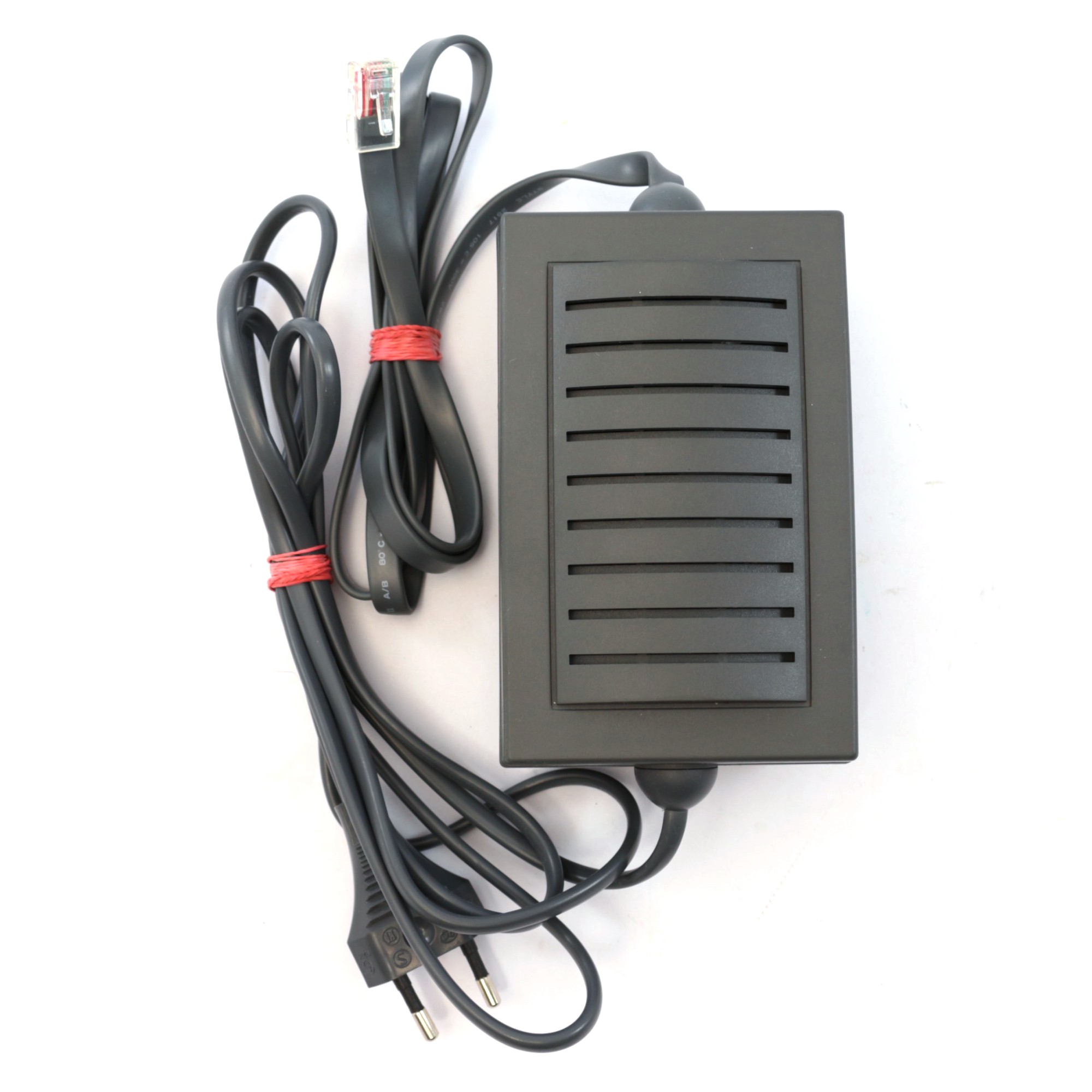
Everybody familiar with ethernet cables knows the plastic tab on an RJ45 plug will snap off sooner or later. Then the plug will become loose and start falling out of the jack. While it might not be that devastating on a network connection, it is unacceptable for a power connection. Not to mention that over the decades, some consoles were separated from their original PSU, and replacements are expensive while supplies being limited.
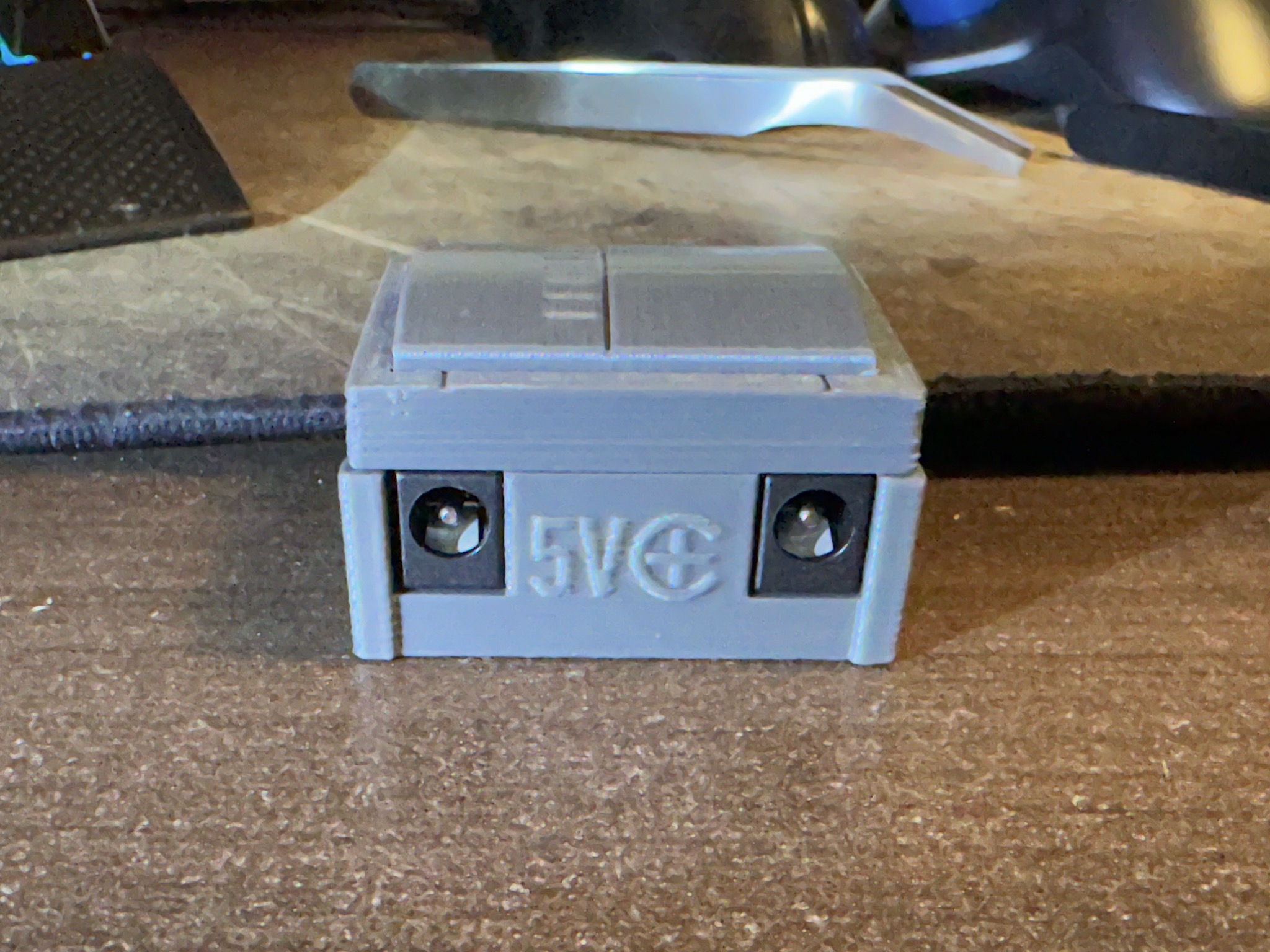
This adapter utilizes TWO Center-Positive 5V power adapters, with the plug dimension of 5.50mm OD (0.217") and 2.10mm ID (0.083").
Do NOT use a Y-adapter with a single power source or your adapter will short and die.
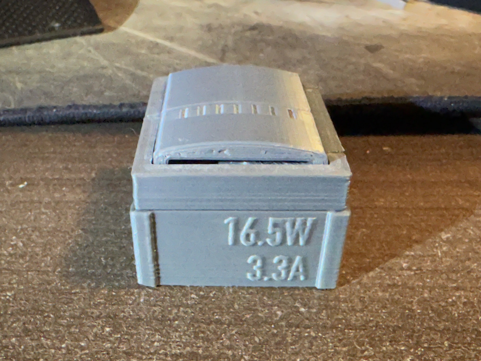
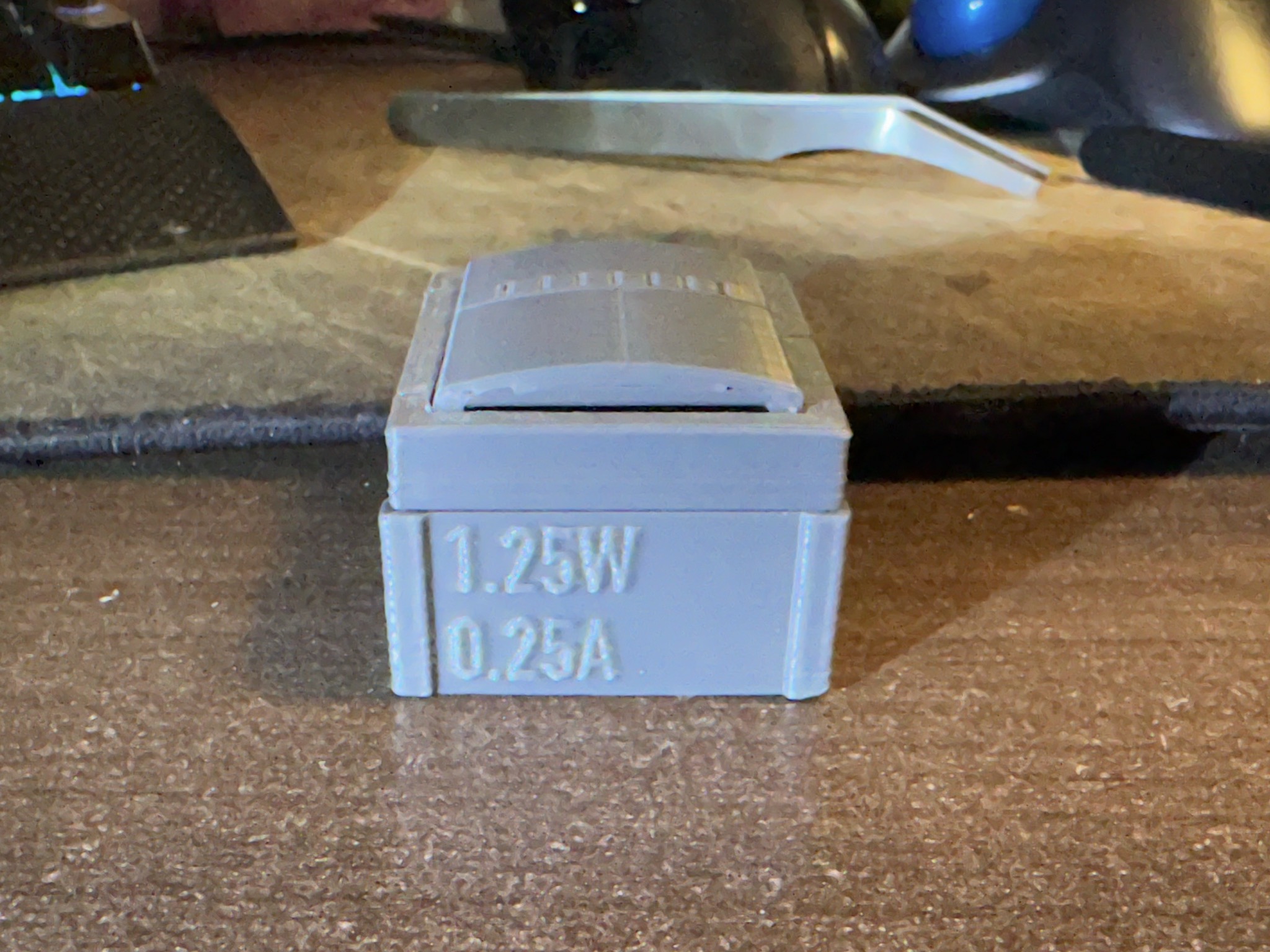
The one on the left requires 3.3A (16.5W). I call this the "beefy" one.
The one on the right is a weak one that any 5V adapter you can find will be more than capable to handle the job.
These power rating specs are the lowest requirements. You can go higher but not lower.
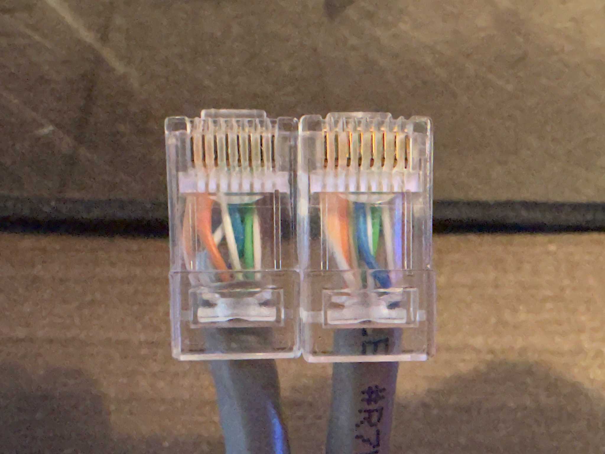
Use a straight RJ45 ethernet cable in short length. The wiring order on the two ends of the cable should be exactly the same or bad things will happen. It's easy to test with a meter if visual inspection is difficult.
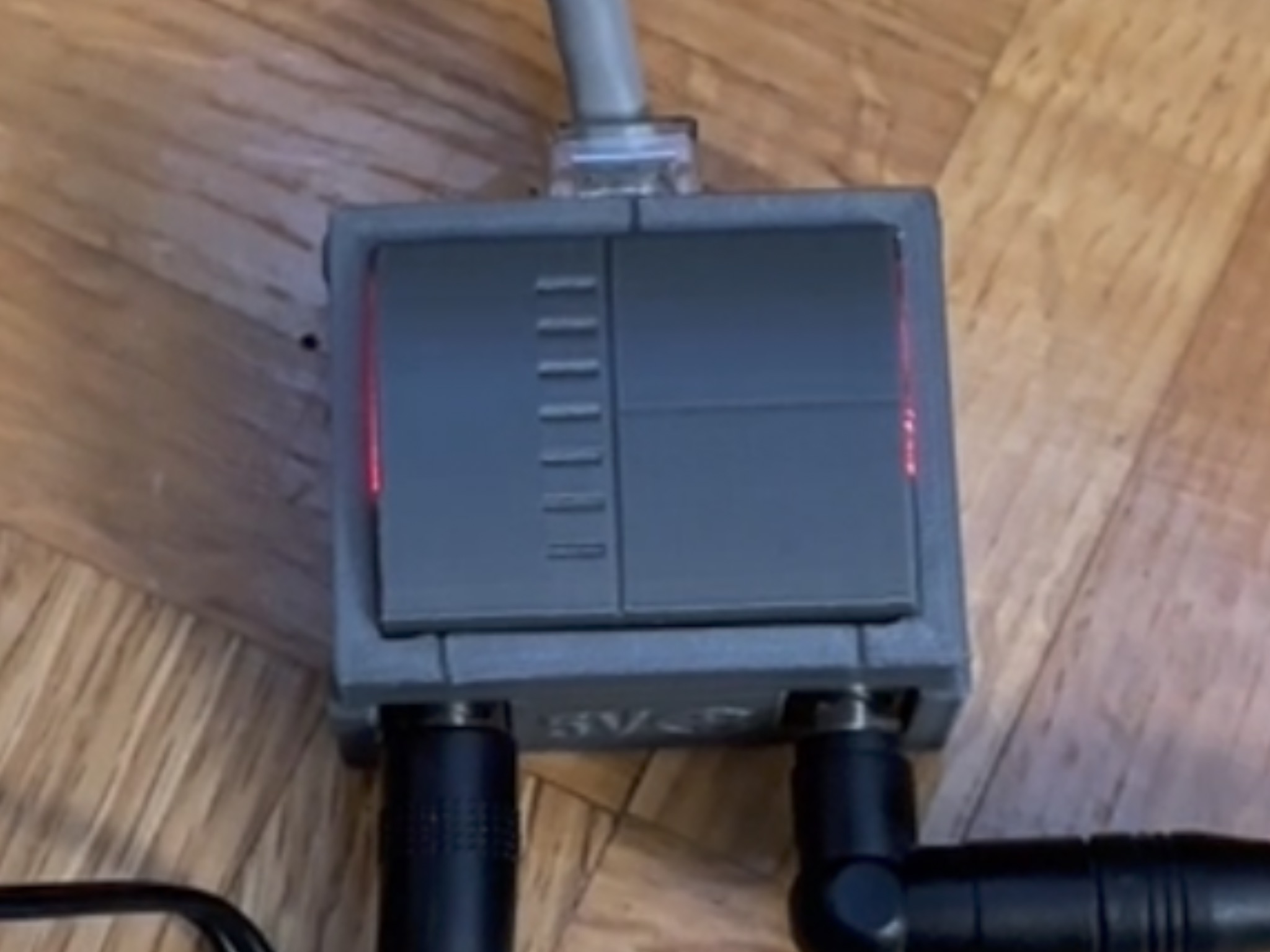
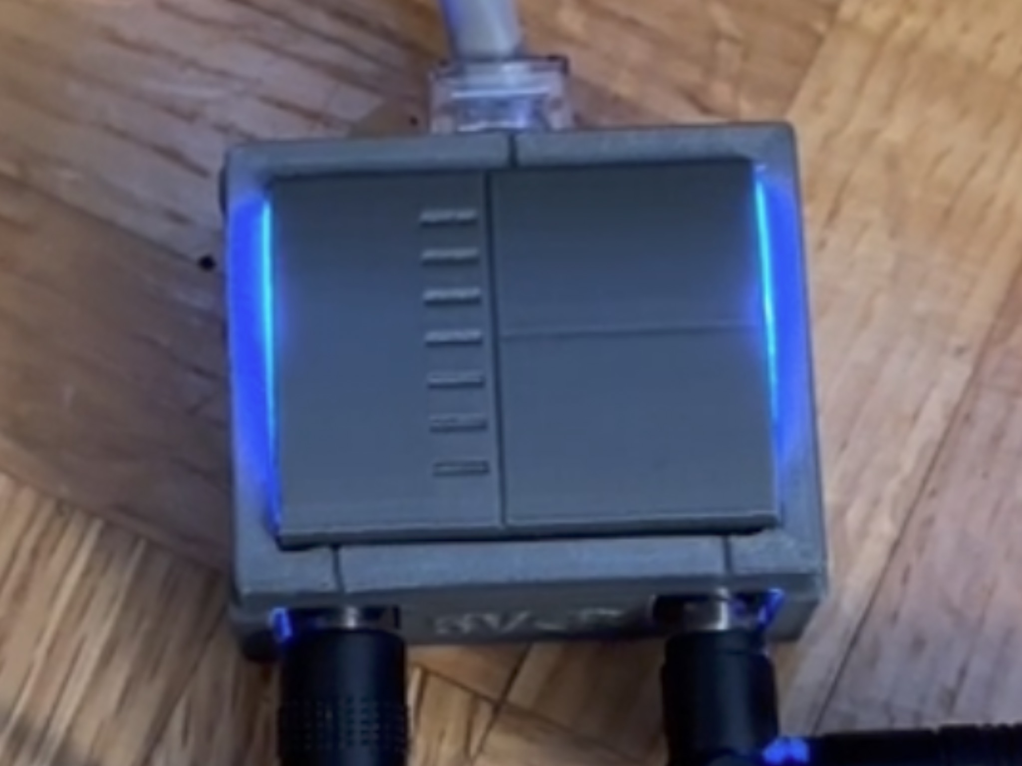
Plug everything in and use the power switch on the CD-i itself to turn the power on/off.
Optional Parts
Print the parts as shown in the following pics, with support.
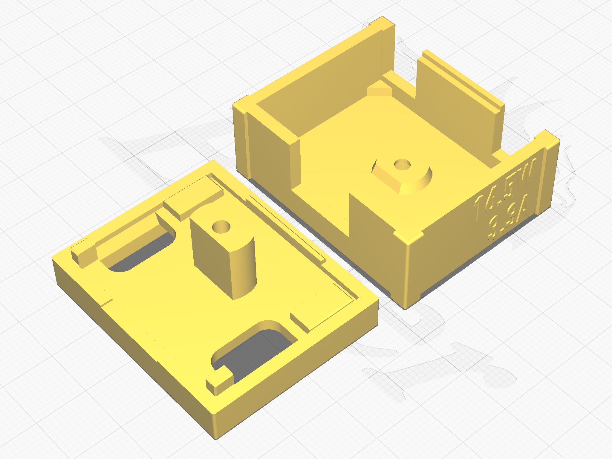
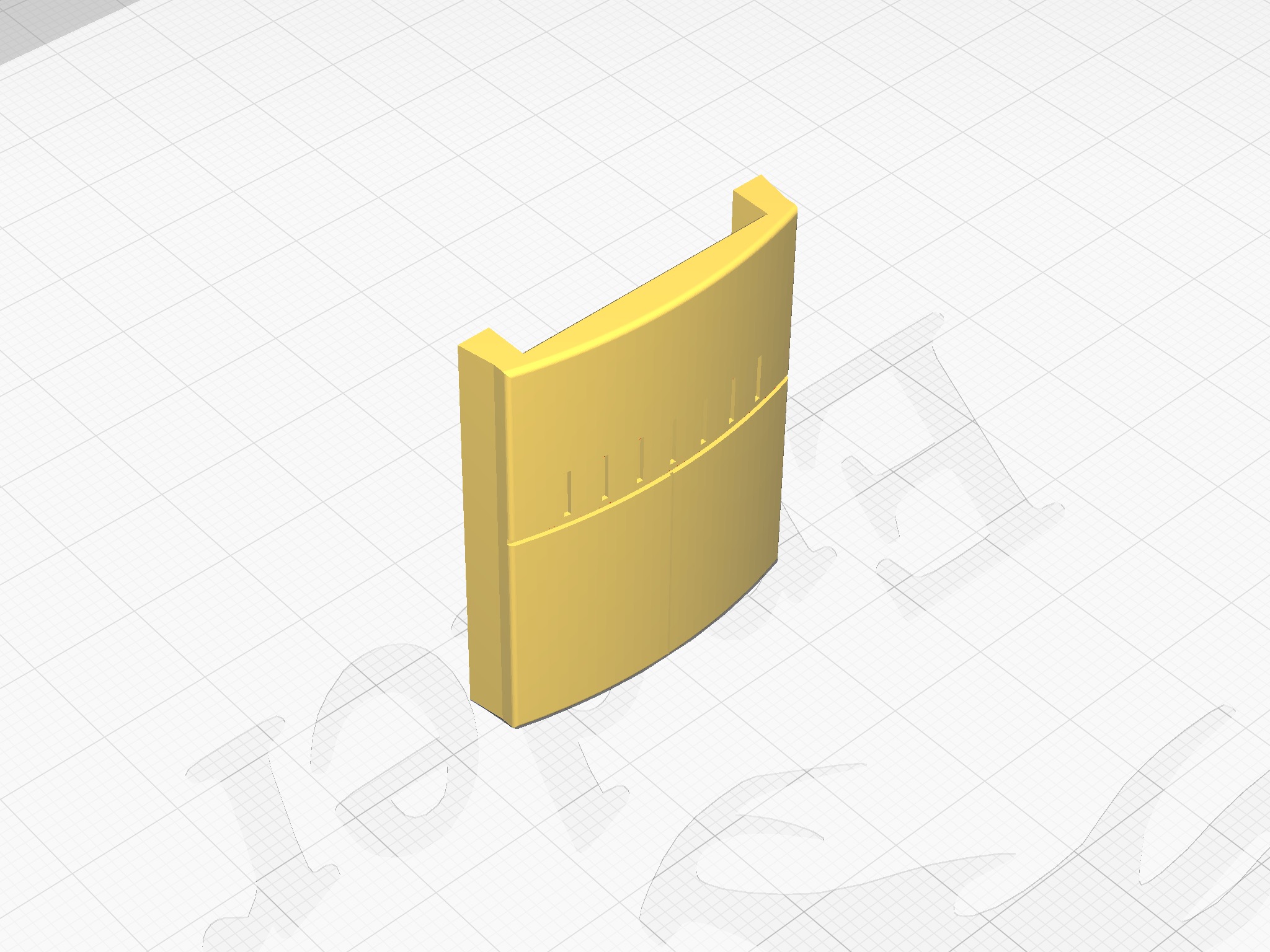
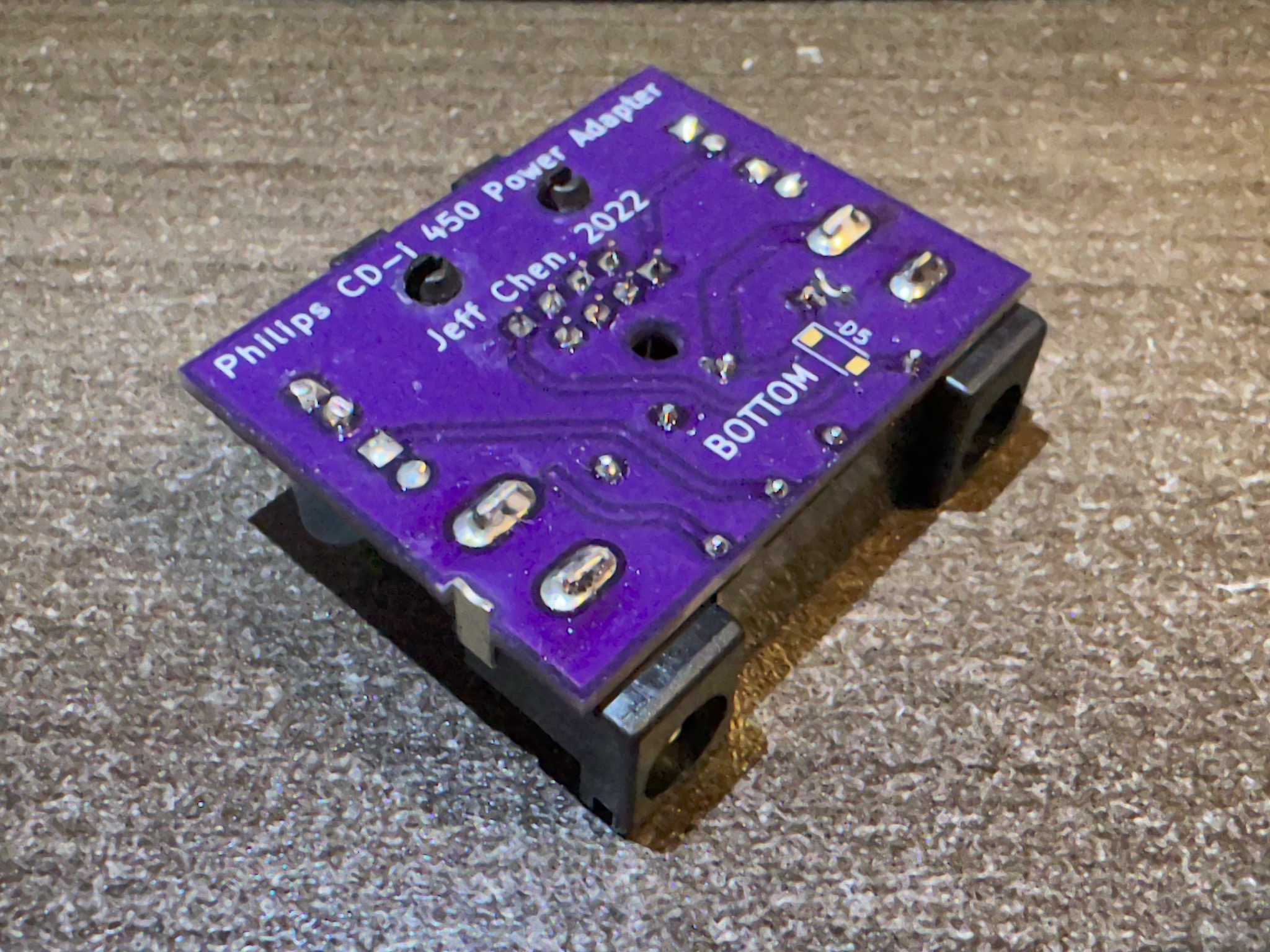
Populate the PCB with parts. Trim the extra length of extruding legs but no need to go crazy.
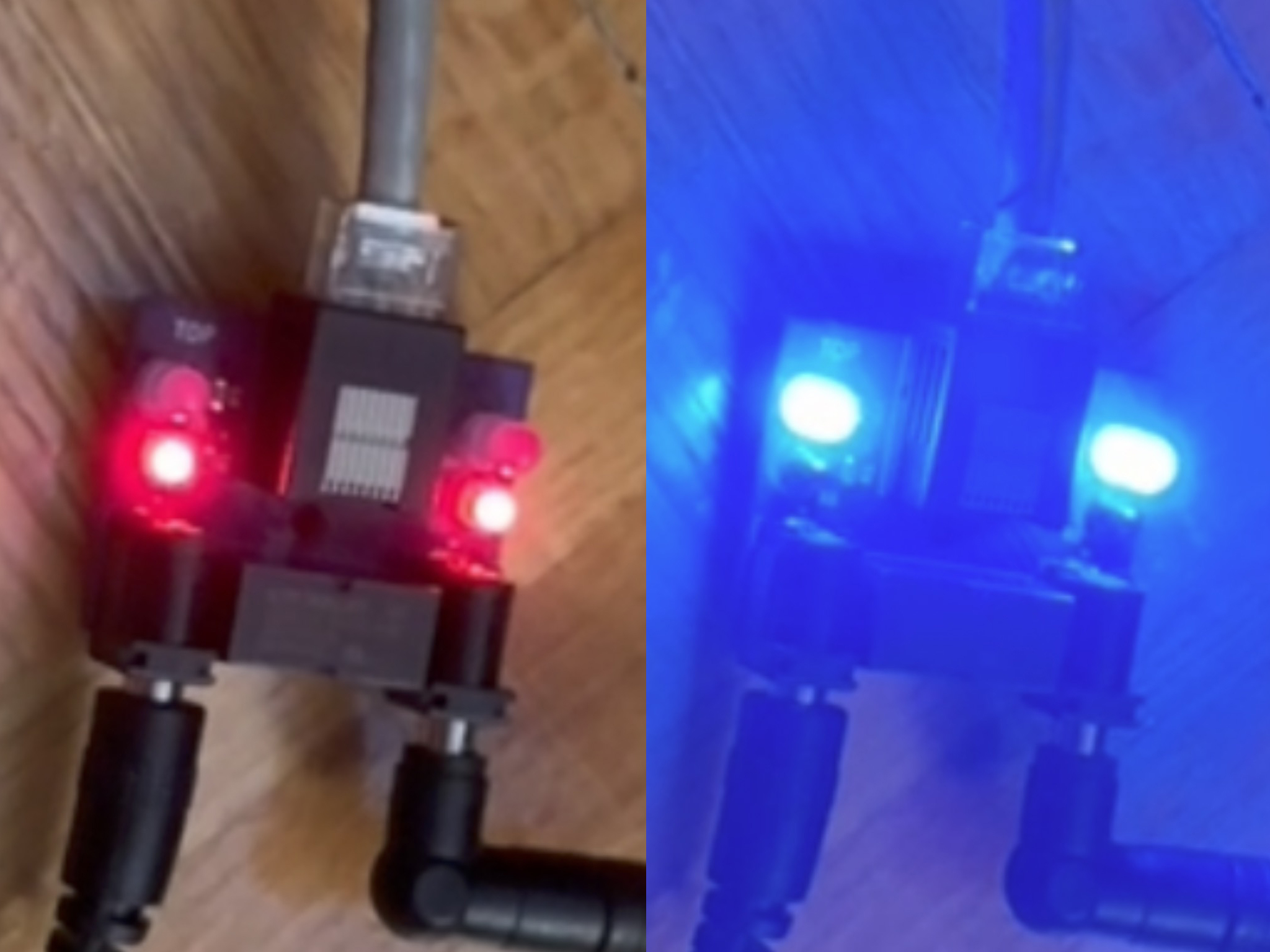
D1 and D2 are for standby and D3 and D4 are for running. Choose your colors accordingly.
If in case one side does not light up, please check your power sources first as there might be a serious problem.
Fit into the bottom shell. Close the top shell over.
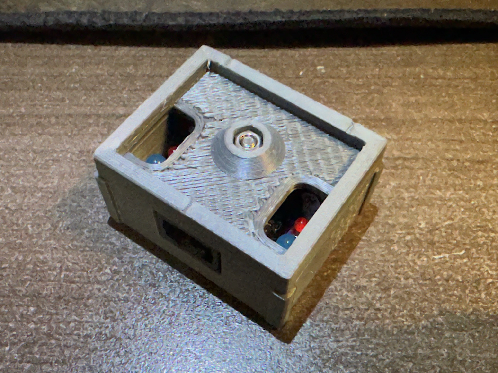
Drop the nut inside the cavity, then tighten the screwn from the bottom.
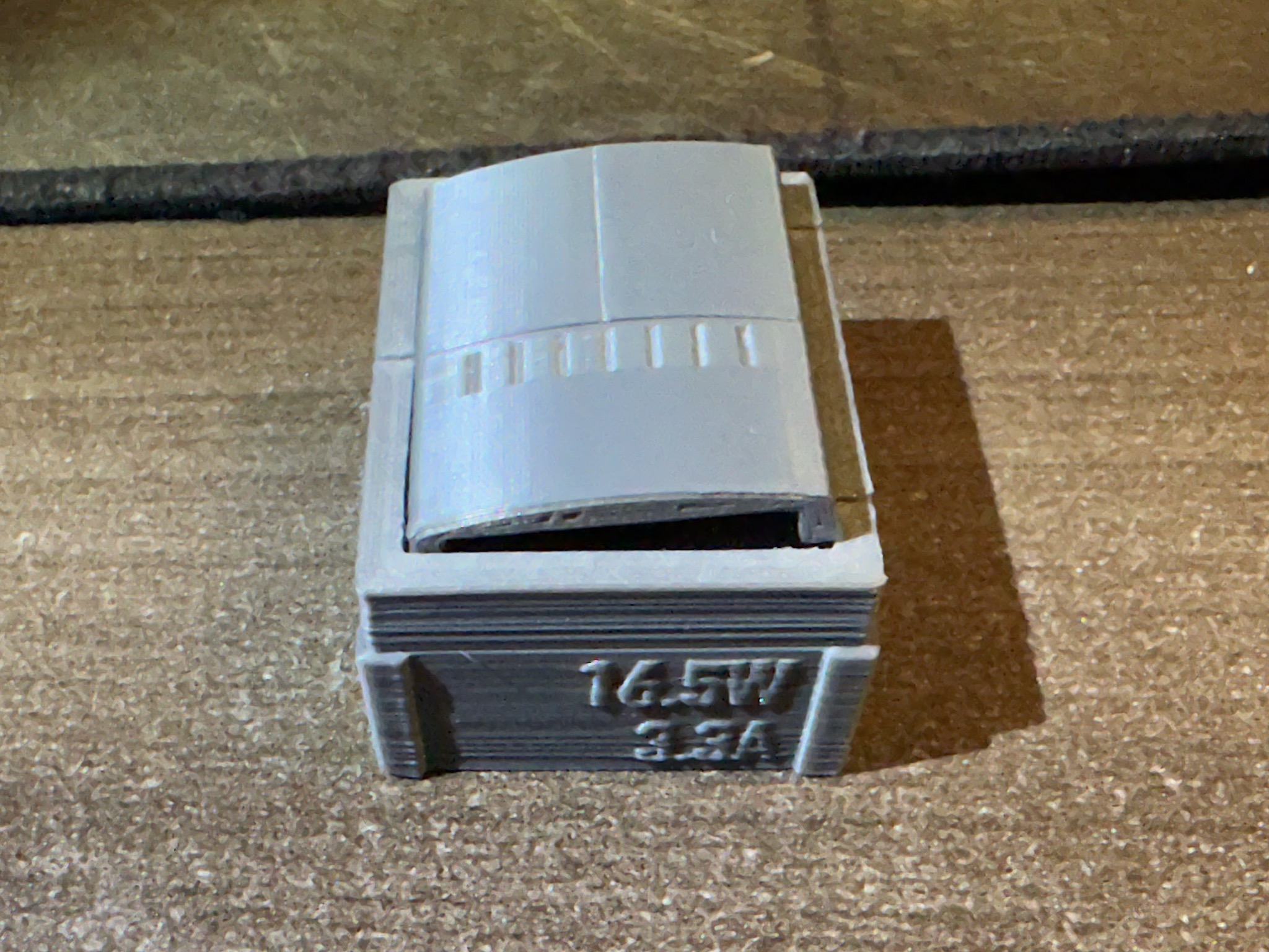
Drop in the top lid inside, fit one side in position first, then press and snap the other side into the slot.
This concludes the assembly.
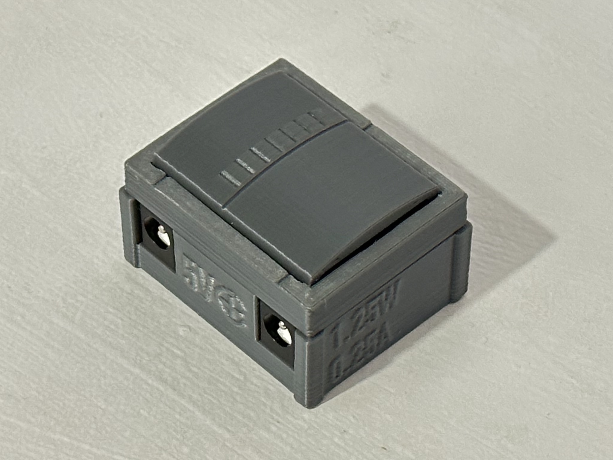
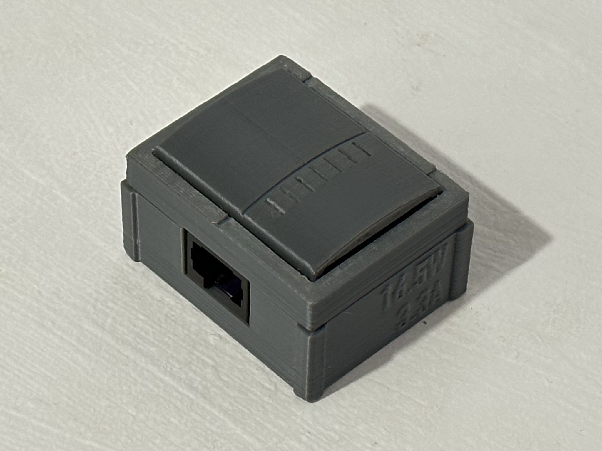
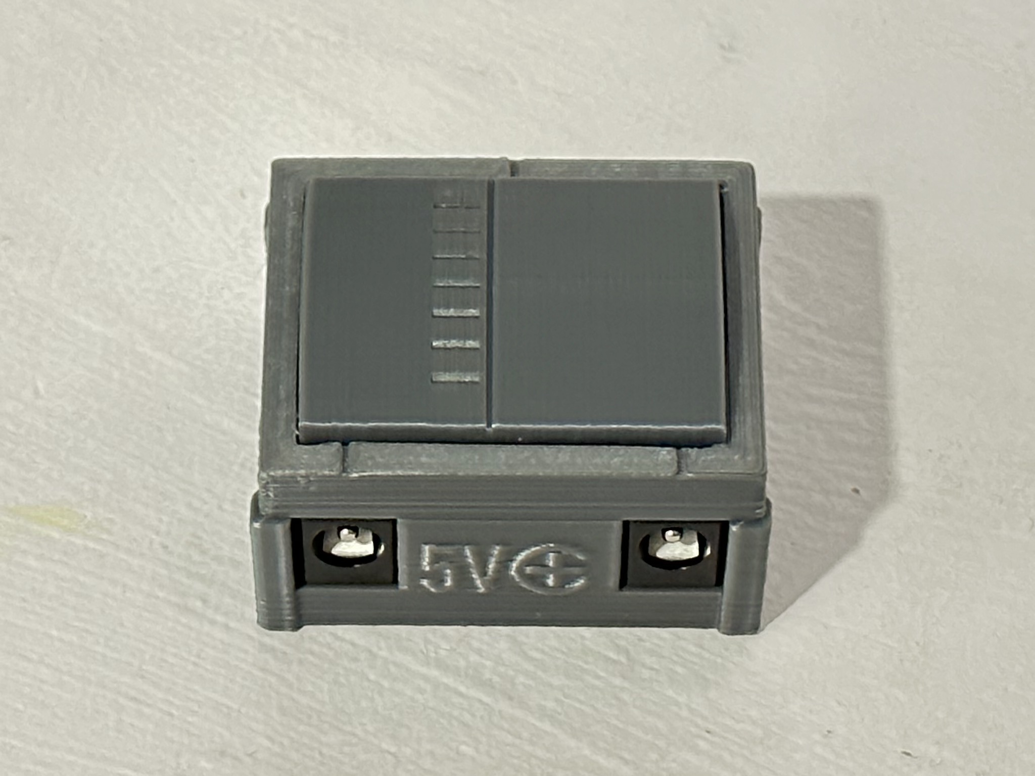
Shield: 
This work is licensed under a Creative Commons Attribution-ShareAlike 4.0 International License.

| Qty | Value | Footprint | References |
|---|---|---|---|
| 4 | 150 | Resistor_SMD:R_0805_2012Metric_Pad1.20x1.40mm_HandSolder | R1, R2, R3, R4 |
| 4 | LED | LED_THT:LED_D5.0mm | D1, D2, D3, D4 |
| 1 | clipboard:47629e3f-1a8b-4431-a5bc-737dc30e2243 | ||
| 1 | 1N4148W | Diode_SMD:D_SOD-123 | D5 |
| 1 | 5V 0.25A C+ | Philips CD-i 450 Power Adapter:CUI_PJ-002A | J2 |
| 1 | 5V 3.3A C+ | Philips CD-i 450 Power Adapter:CUI_PJ-002A | J1 |
| 1 | RJ45 | Philips CD-i 450 Power Adapter:RJ45 | J3 |
| 1 | Relay | Philips CD-i 450 Power Adapter:Relay | RL1 |
NEOgHacking/DMXion_4Port_Node
A 4 port dmx node with rdm funtionallity. Connects via ARTNET or sACN

PKCubed/speed-rj45
A game in which the player's compete to correctly terminate rj45 connections the fastest.


UtilitechAS/amsreader-firmware
ESP8266 and ESP32 compatible firmware to read, interpret and publish data to MQTT from smart electrical meters, both DLMS and DSMR is supported
It measures 40.2 × 31.2 mm and has 2 copper layers, 1.6 mm thick.
14 parts, built around the 1N4148W and RJ45. The full list of its parts is on this page, with links to each part's symbol and footprint where PCBKit's library has them.
From the jeffqchen/Philips-CDi-450-Power-Adapter repository on GitHub, at the commit this page was made from: the board is KiCAD/Philips CD-i 450 Power Adapter.kicad_pcb and its schematic KiCAD/Philips CD-i 450 Power Adapter.kicad_sch. PCBKit opens the board in the browser, with nothing to install.
Its repository publishes it under the CC-BY-SA-4.0 licence: you may reuse it on that licence's terms (keep the author's notice, and for a copyleft licence share your changes alike).