2 layers20.5 × 24.8 mm

 jeffqchen/PSone-Filament-LCD-Backlight-Mod20
DIY Backlight mod that uses the new filament LED strips.
PSone Filament LCD Backlight Mod is an open-source printed circuit board by jeffqchen, from the jeffqchen/PSone-Filament-LCD-Backlight-Mod repository on GitHub, published under the CC-BY-SA-4.0 licence. It is a 2-layer board of 33.5 × 8.5 mm with 8 parts on 6 nets, routed with 31 tracks and 1 via.
Its parts include 5 resistors, 2 connectors and 1 IC. It belongs with the lEDs and displays boards of this library.
The official PSone LCD screen has a fragile backlight system. The inverter and the CCFL tube could kick the bucket on itself. Sometimes you can't even figure out what went wrong with the backlight system. It's also nearly impossible to find the exact replacement parts at a reasonable price, even if you managed to figure it out.
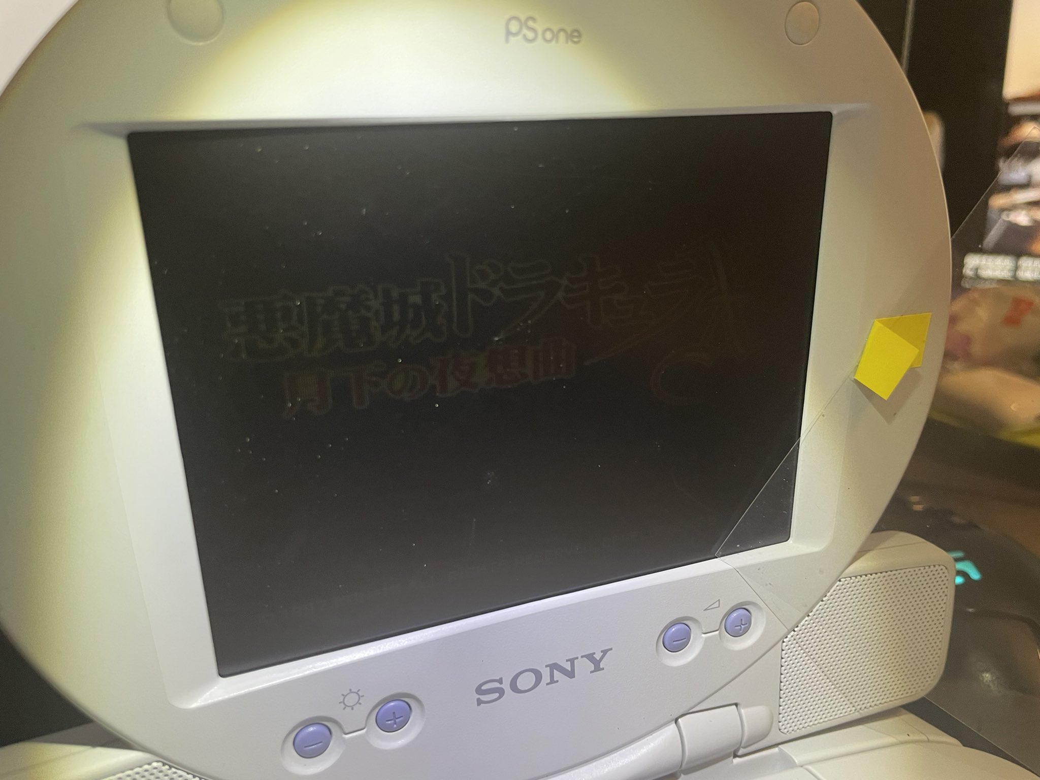
Previously, there were multiple attempts of similar mods. But they all used singular LEDs, and resulted in uneven backlight that's difficult to look at. This new type of flexible filament LED provides the uniformity as good as the CCFL tube, and is very easy to manipulate. More importantly, they are very affordable.
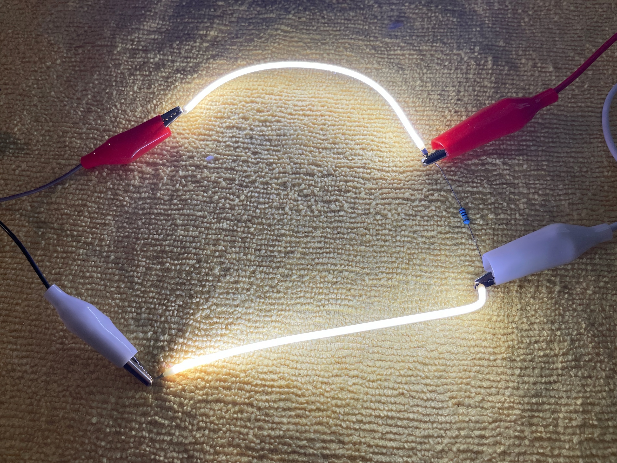
So here is my solution, just in case you are facing the dilemma (however, by all means, please try to diagnose and fix the original system if possible).
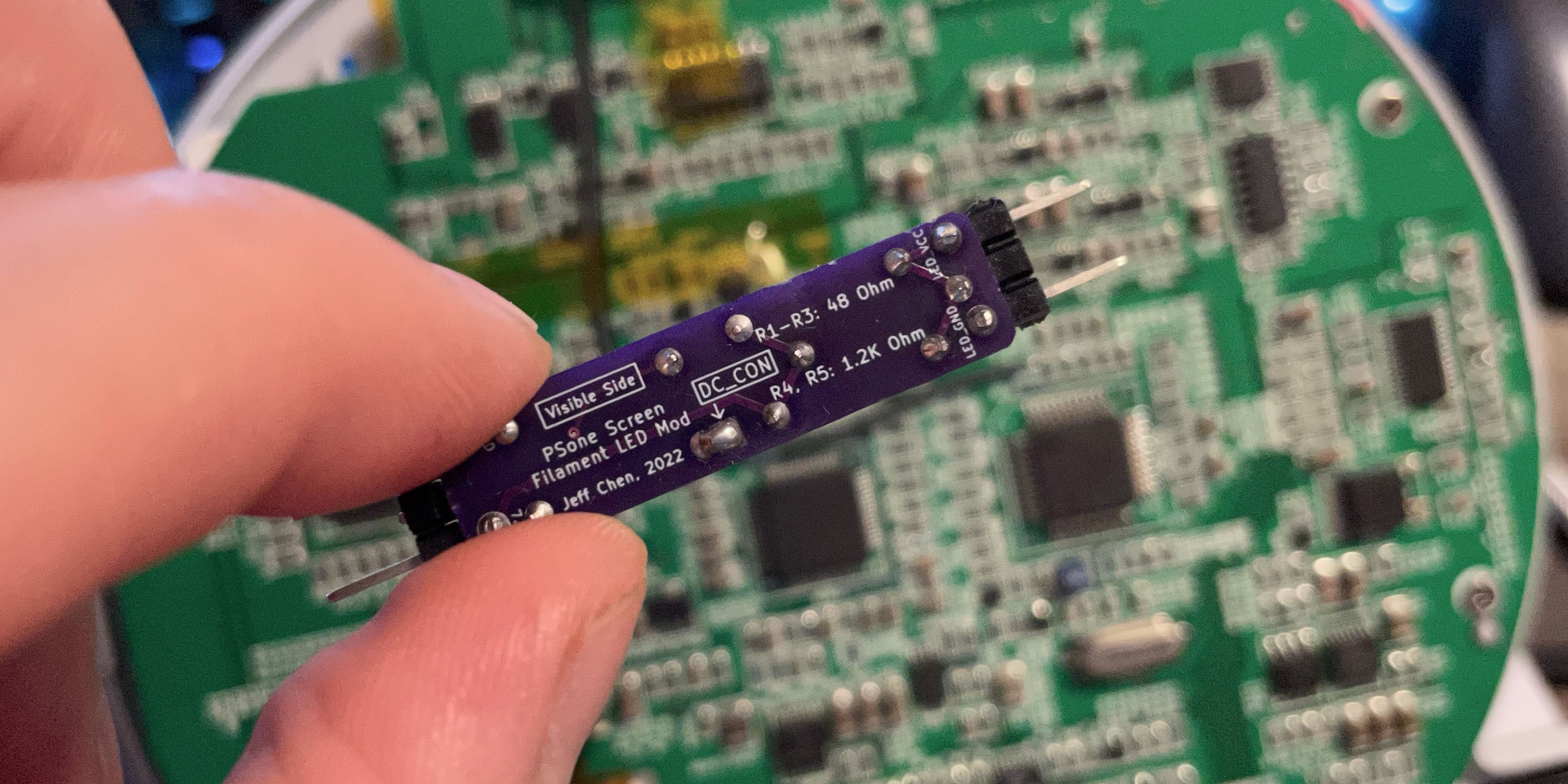
This design takes the 7.5V from the power input, runs it through an NPN amplifier, to feed power through two 3V flexible filament LED strips and some current-limiting resistors, controlled by the 5V_CON signal from the console.
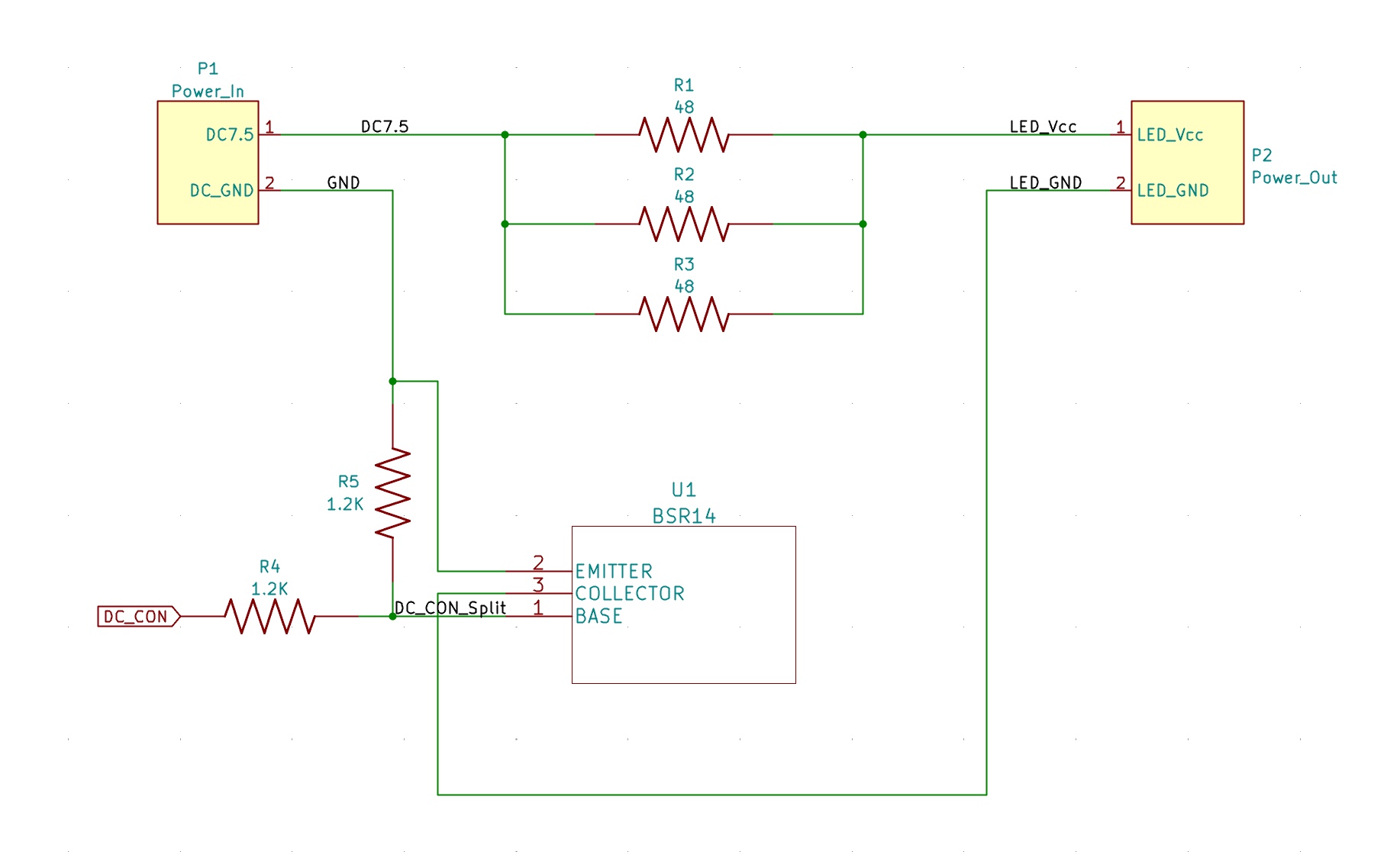
Please note these values were fine tuned and do not match the perfect calculations. Somehow these filament LED strips do not drop the claimed voltage and I had to reduce the value of the current-limiting resistors to make them emit enough light. I did let the system run for an extended period of time to make sure it would last. The operation temperature was still much lower than the original design.
BSR14 NPN Amplifier / SOT23-3 - Link
[2x] Flexible Filament LED Strips, 130mm, DC 3V, Cold White 6500K - Link
2.54mm-Pitched Pin Header, Right Angle - Link
All resistors are 1/4W through hole resistors.
Nothing is special about populating the parts.
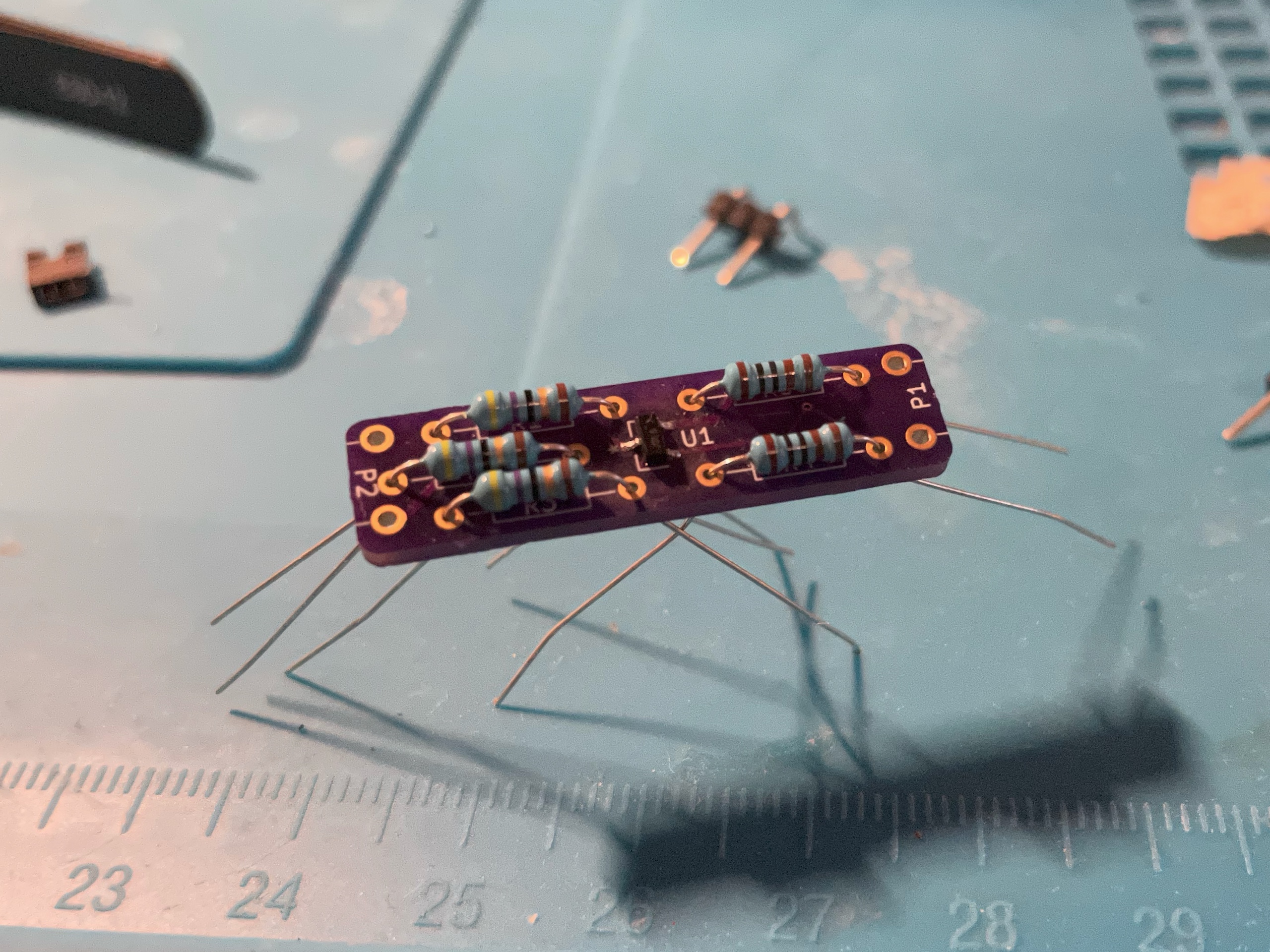
Make sure the right-angled pin headers are on the invisible side of the PCB.
Only two pins are necessary on each side of the PCB.
Note you need 3 pins in a row but have to skip the middle one. You might want to cut off the middle one before hand.
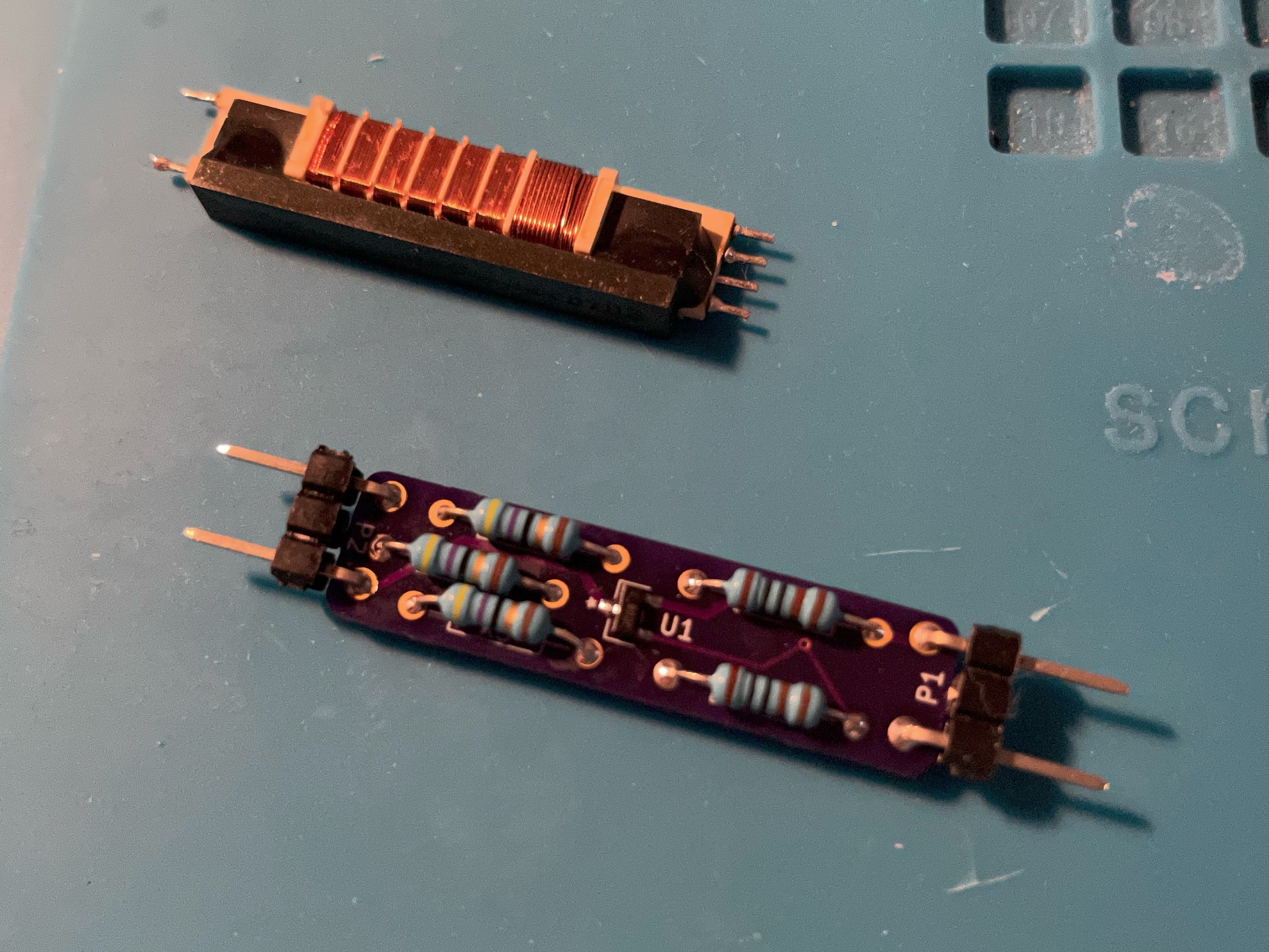
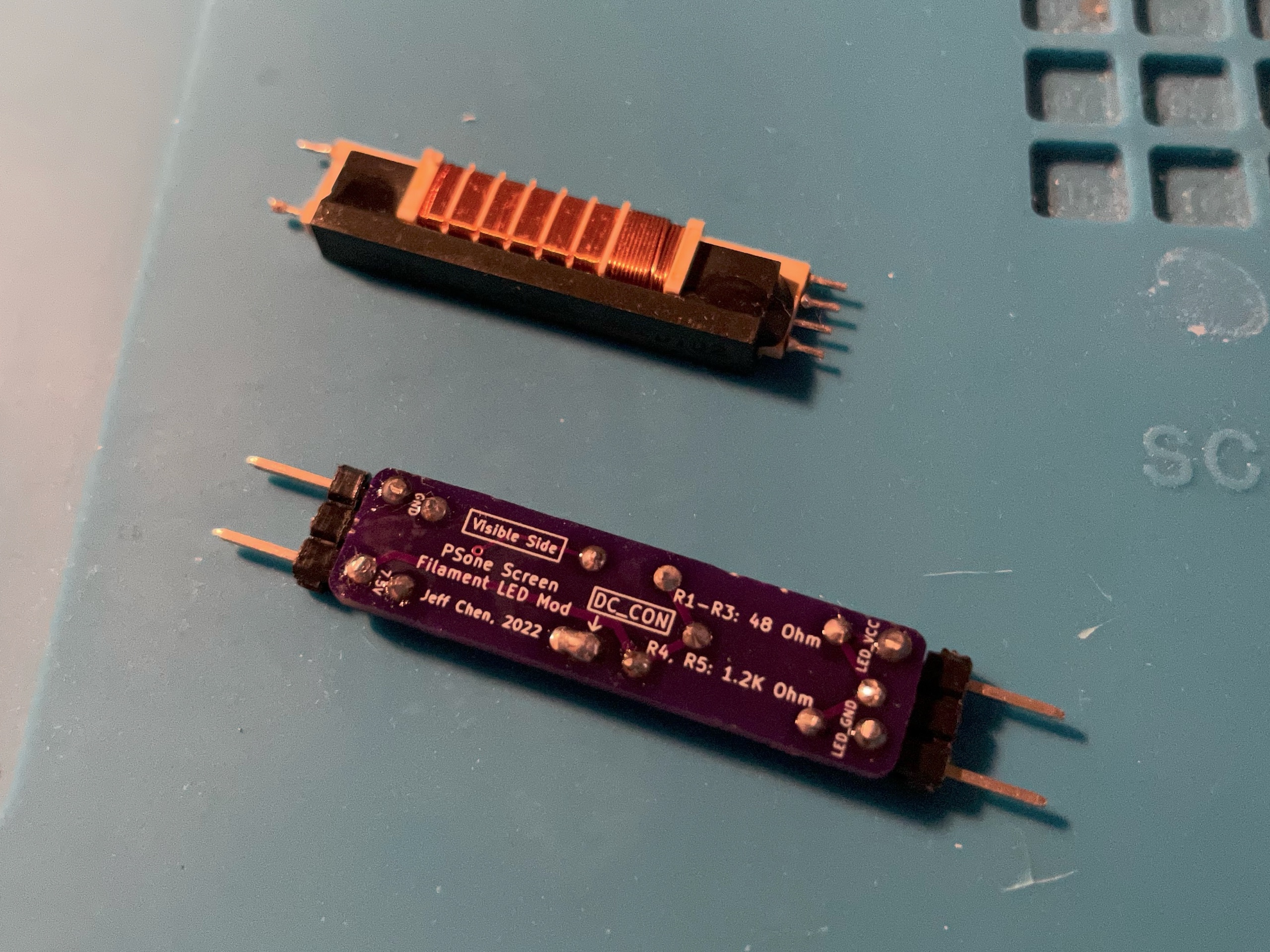
Cut and remove the black spacer after the pins are soldered in place.
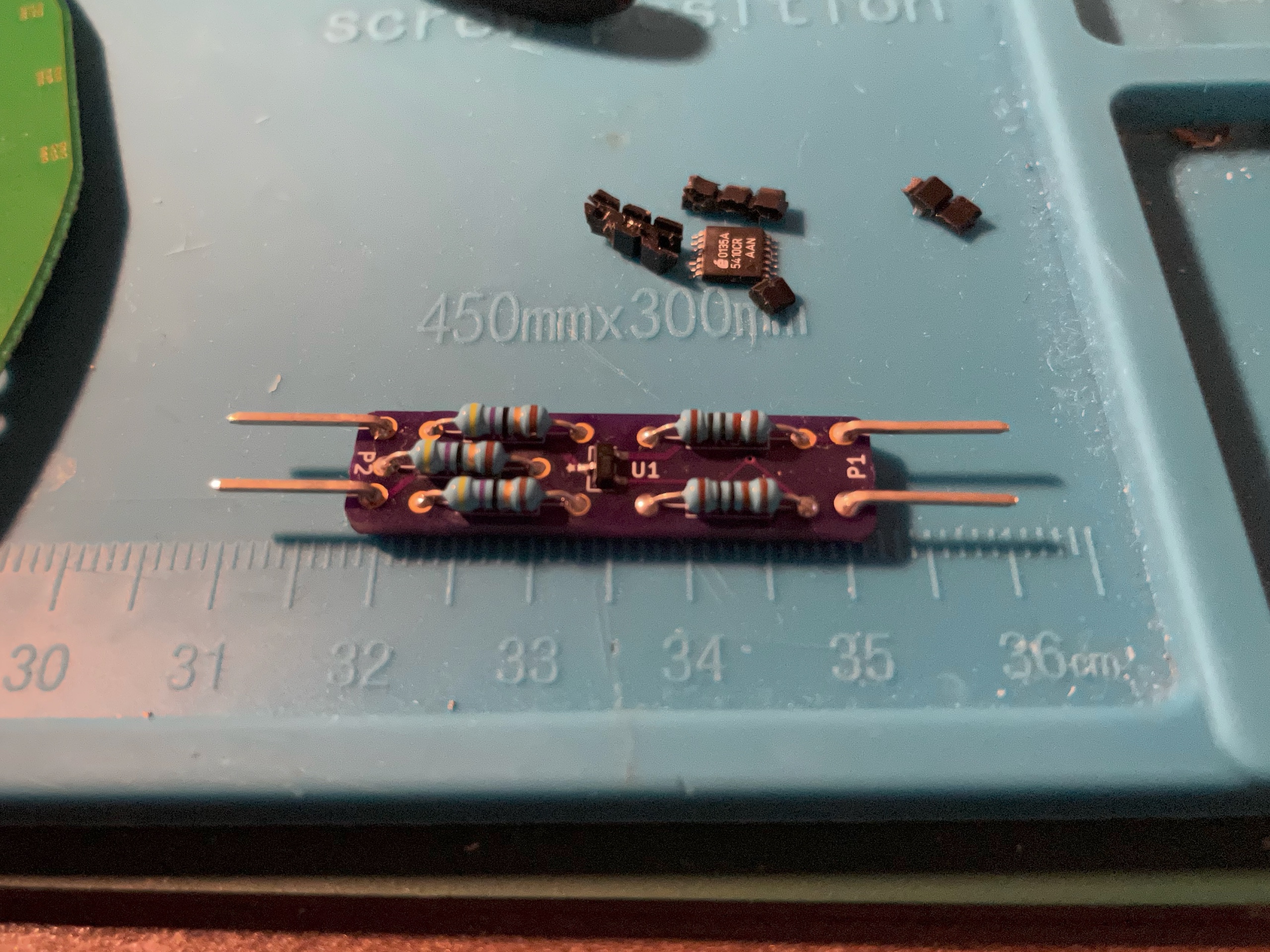
Trim the legs somewhat so they don't reach too far into the main PCB when installed.
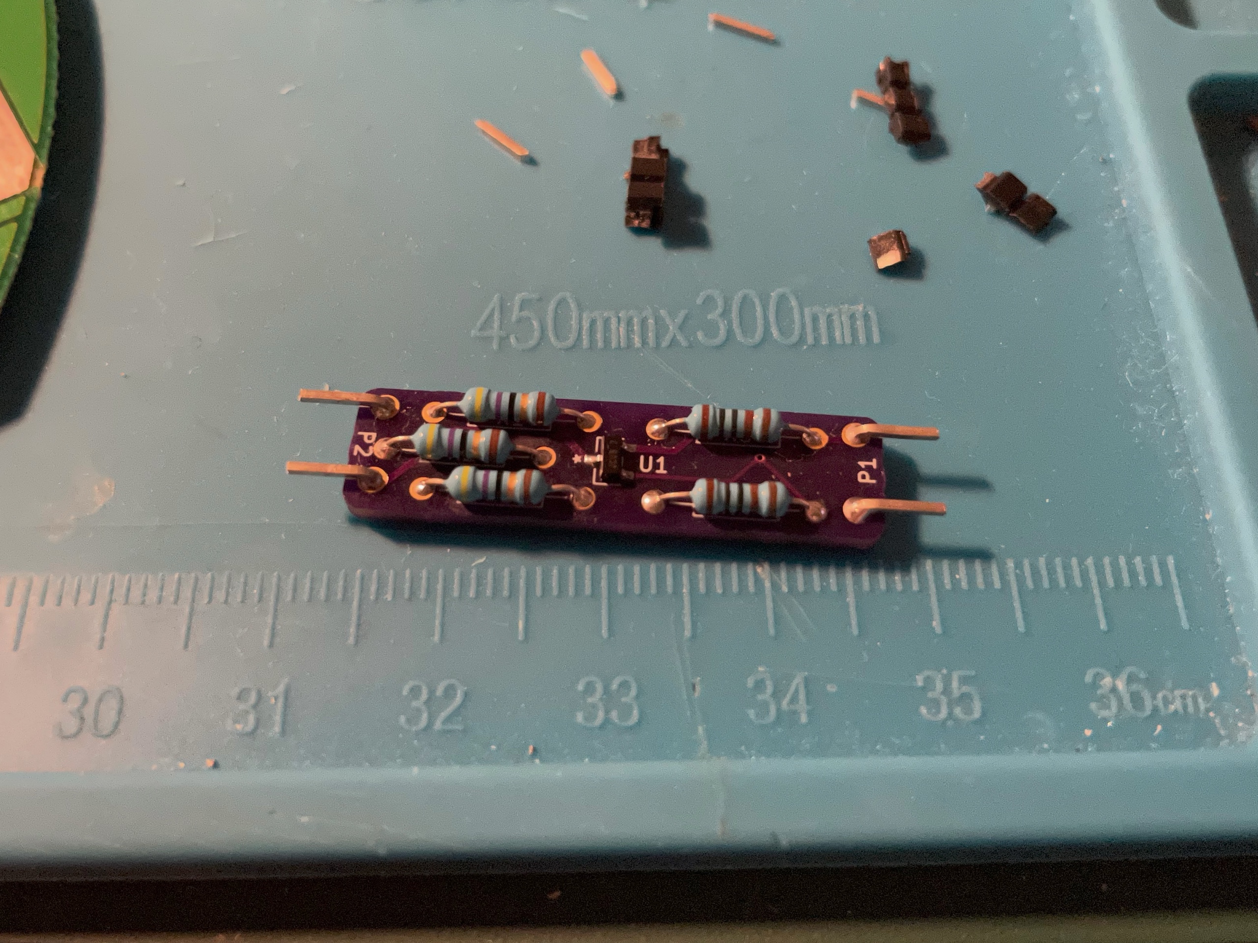
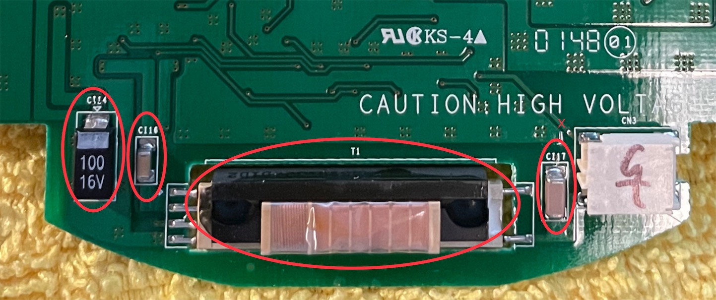
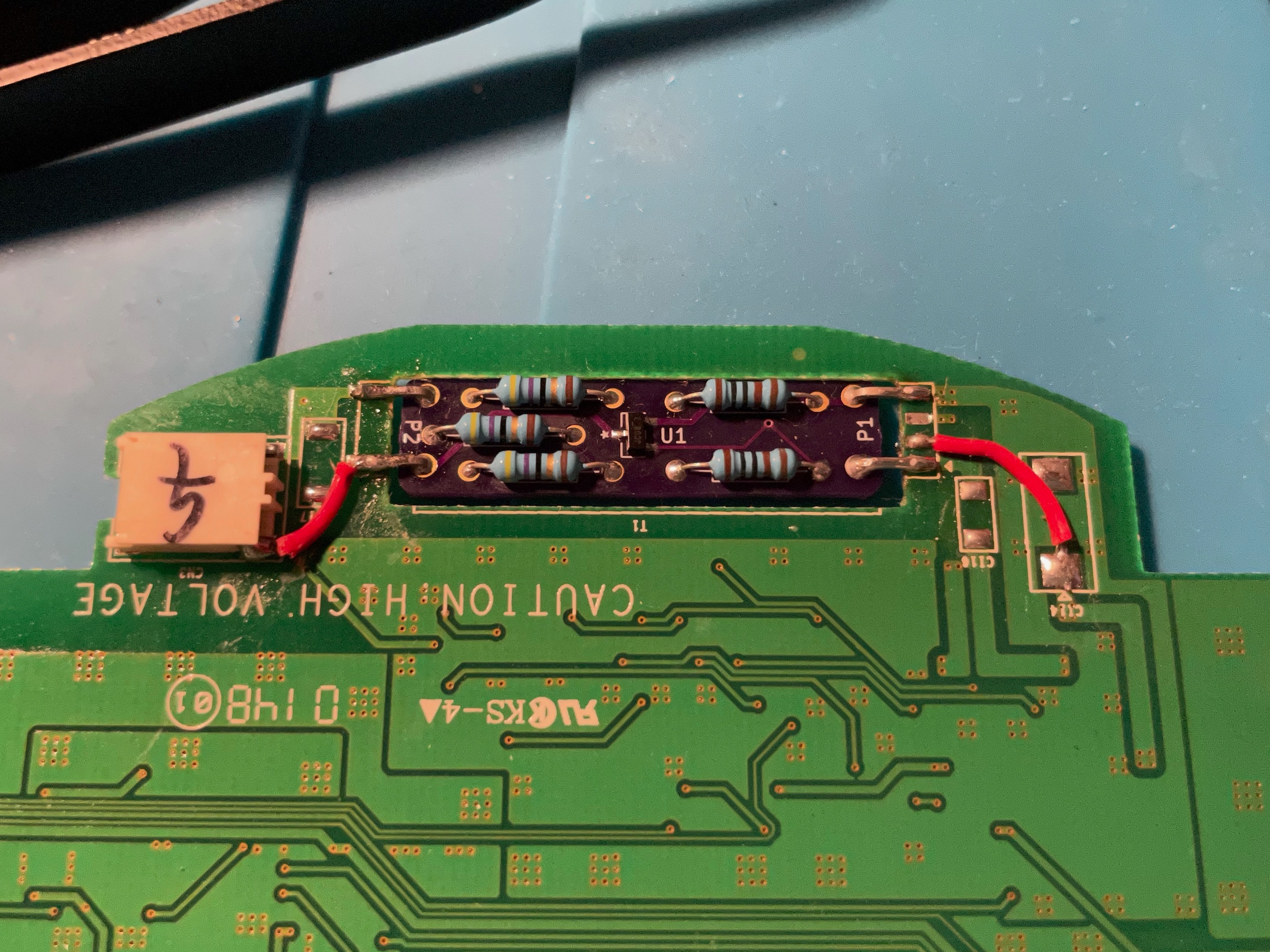
Solder the pin headers to the inside of the motherboard as shown in the photo.
Solder two jumper wires as shown in the photo.
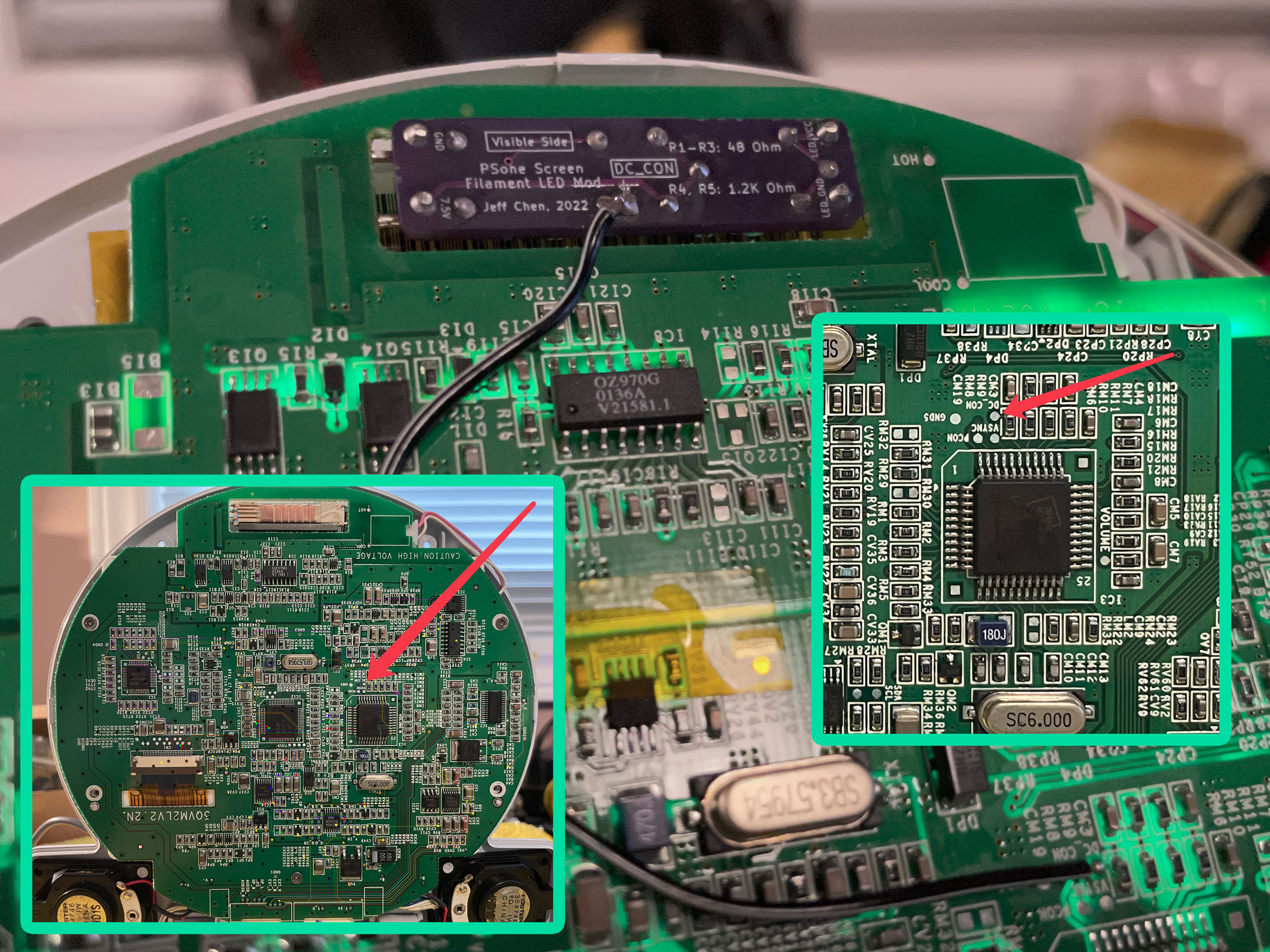
Solder a wire to test point DC_CON on the motherboard, and solder the other end to the DC_CON on the mod board, as indicated in the photo.
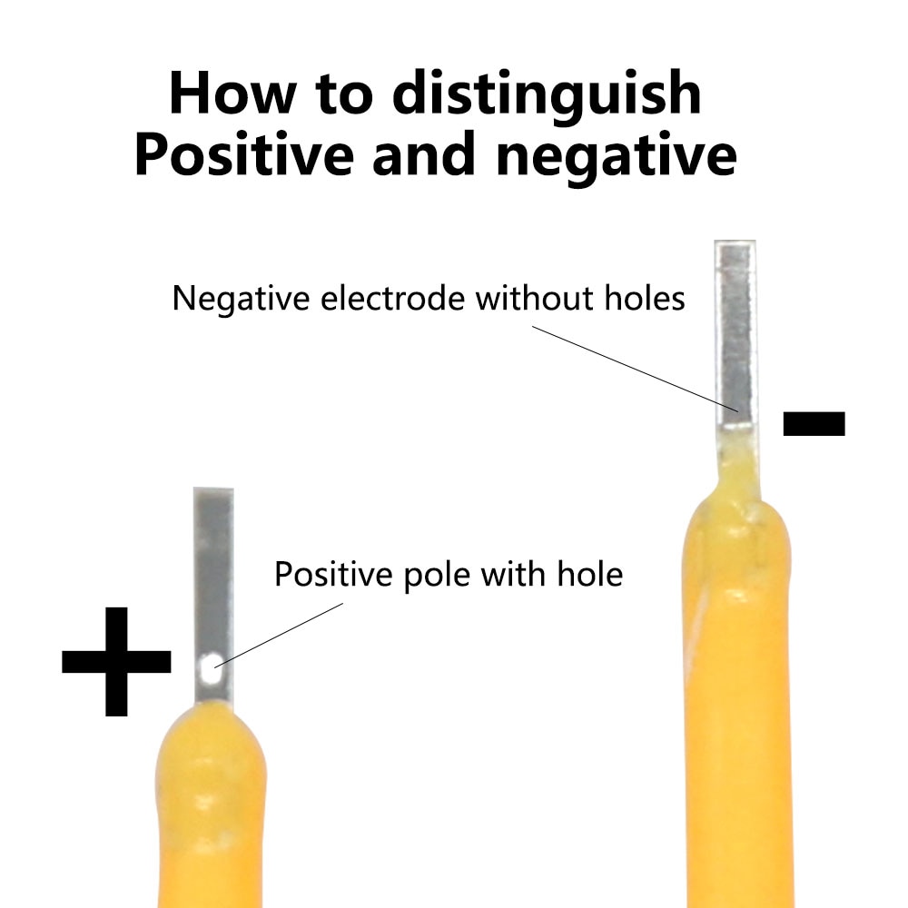
Solder TWO flexible filament LEDs in series with a 60mm-long wire connecting them in the middle.
The polarity of the LED strips is important and requires attention.
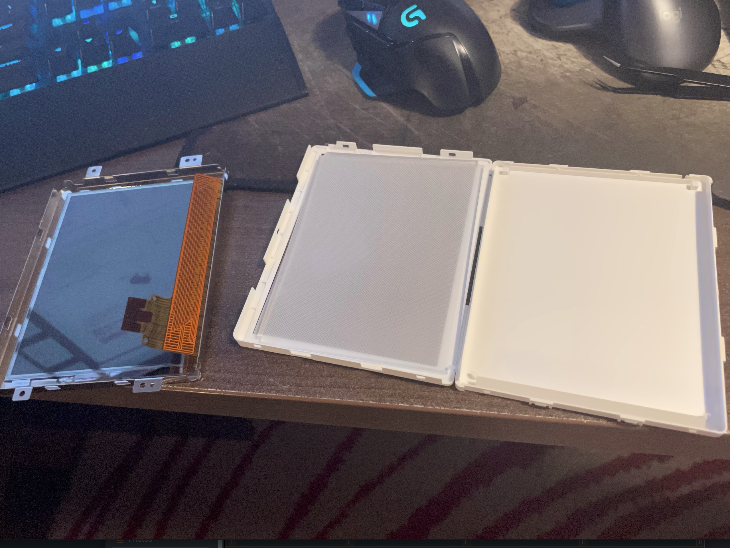
Disassemble the screen, and open up the backlight box assembly.
VERY CAREFULLY remove the CCFL tube.
Desolder the plug from the tube.
Store the CCFL in a rigid environment so it doesn't have the chance to break.
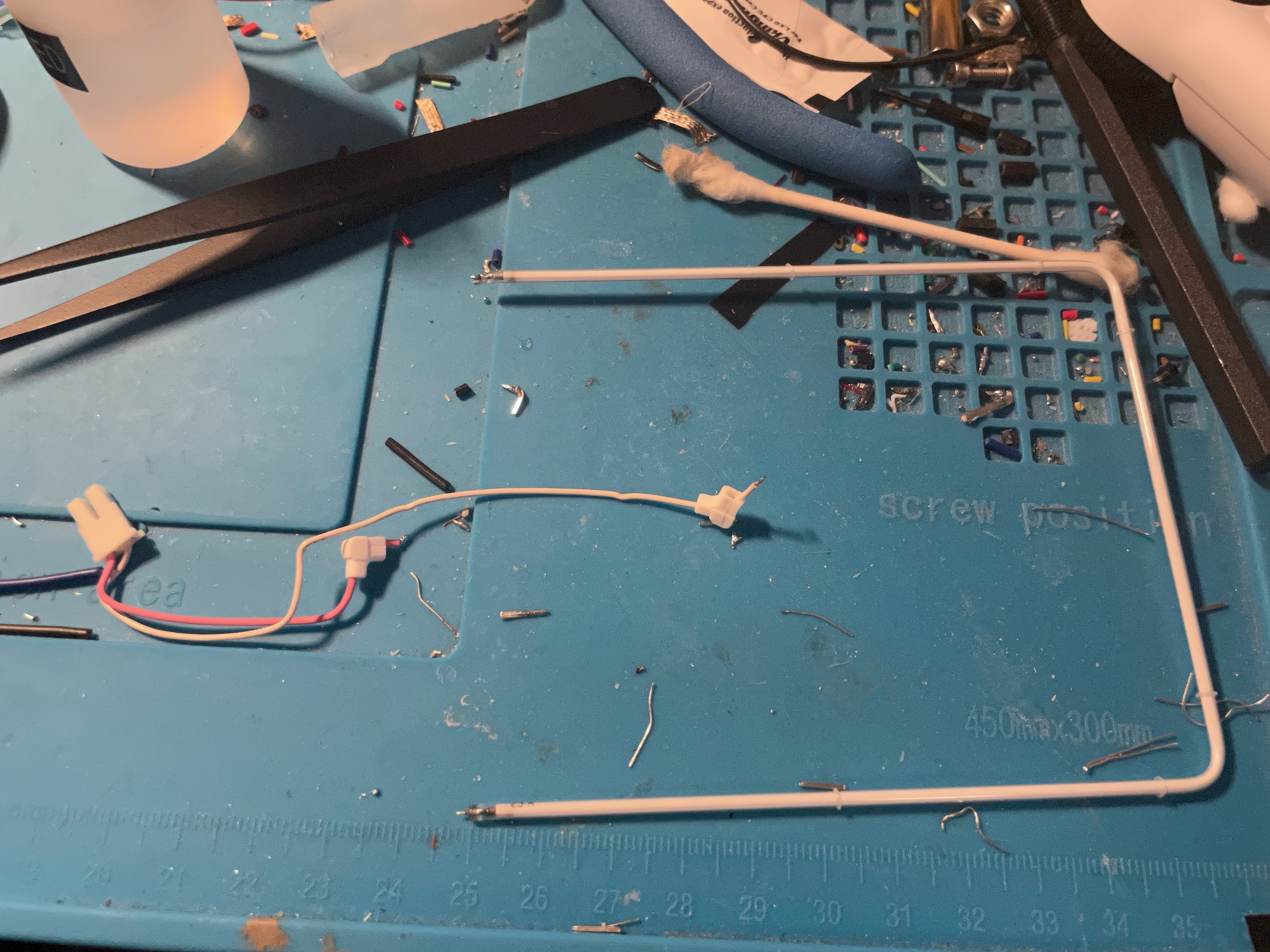
Solder the red wire to the positive end of the LED filament in series, and the white wire to the negative end of the other LED.
If you decided not to use the original CCFL plug, solder the positive end to the upper pin on the mod board with a piece of wire, and the negative end to the lower one with another.
Fit the new LED assembly back into the backlight box like the original, then reassemble the entire LCD screen assembly.
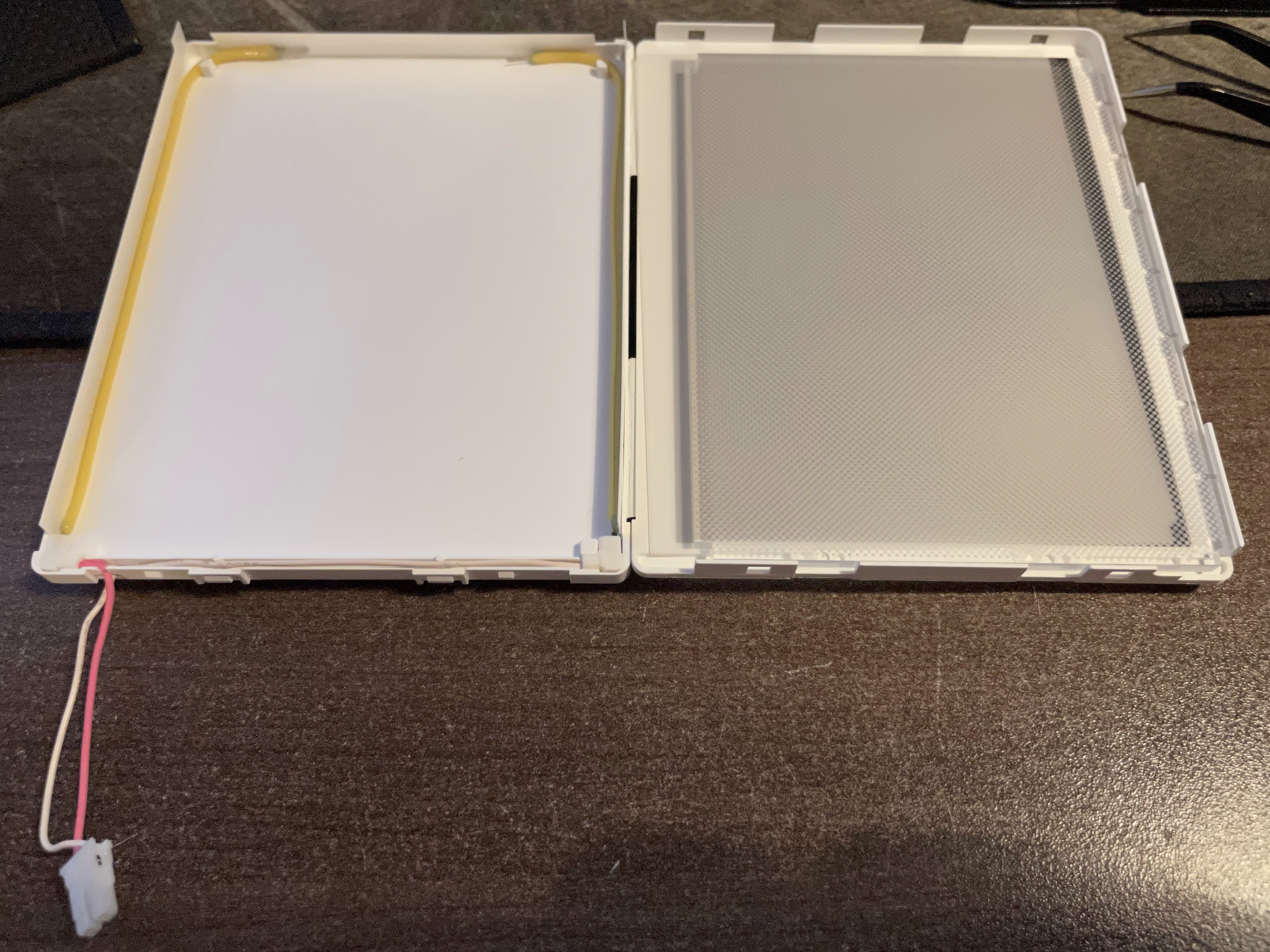
Reseat the screen into the shell.
Reseat the motherboard onto the back of the screen assembly, then plug in the screen ribbon cable and lock the tab. Plug back in the screen backlight header.
To safely test the machine, secure the motherboard with at least two screws so the screen doesn't fall apart and cause damage.
The backlight should now work. The backlight will not turn on until the PSone is powered on, exactly like how the screen is supposed to work.
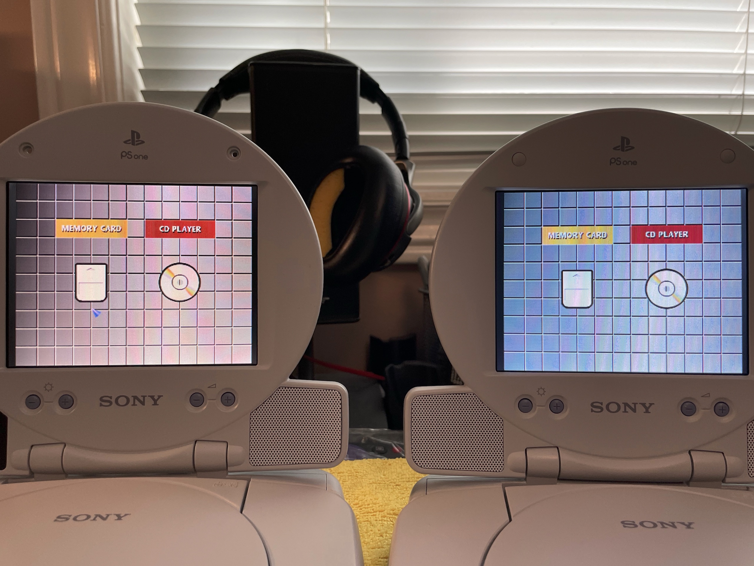
The uniformity of the new backlight should be great - exactly like the original CCFL.
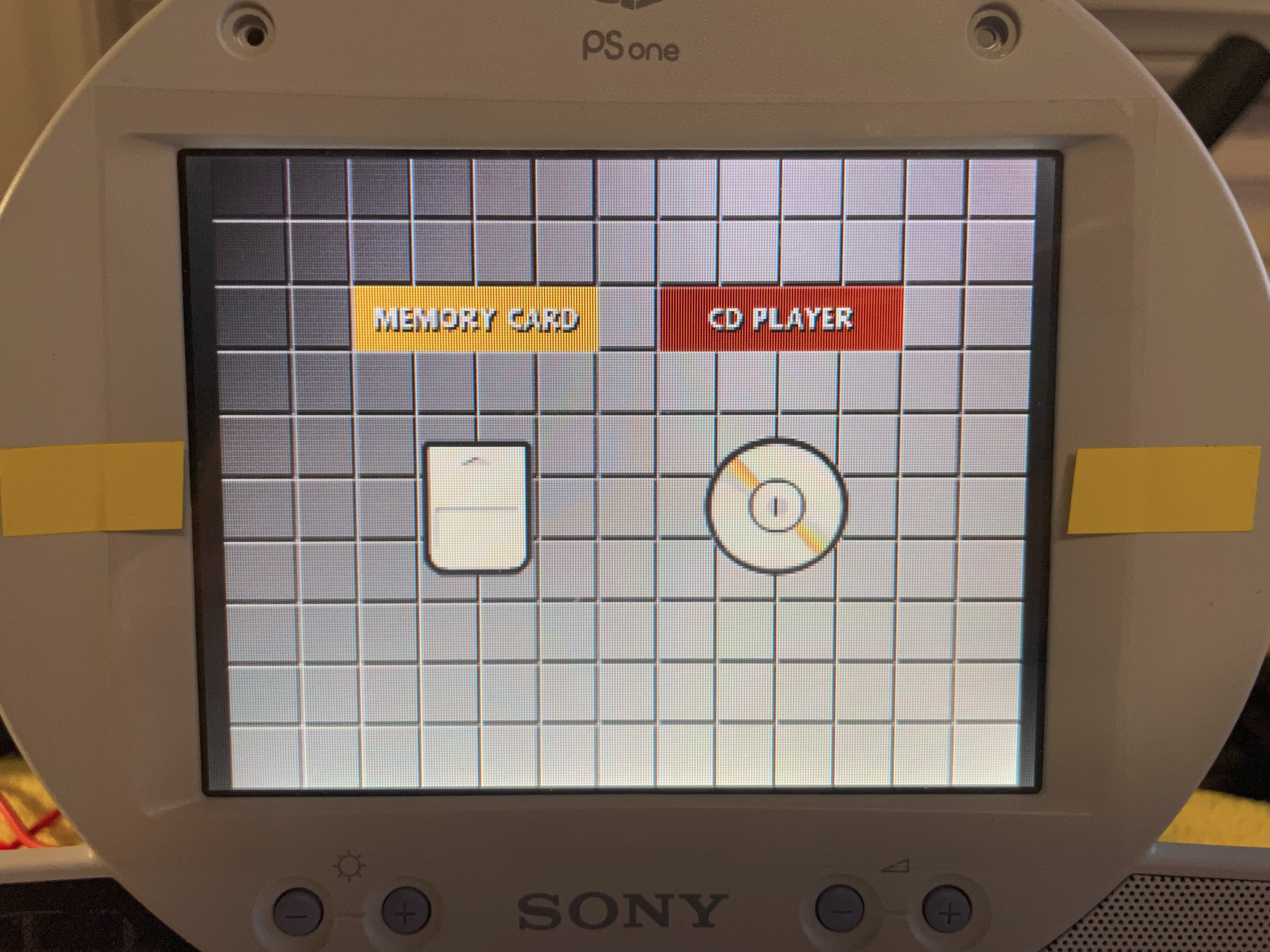
The color temperature of these filament LEDs is different from the original, as compared below. Personally I think the original CCFL was too blue and the LEDs look more natural.
Shield: 
This work is licensed under a Creative Commons Attribution-ShareAlike 4.0 International License.

| Qty | Value | Footprint | References |
|---|---|---|---|
| 3 | 48 | PSone Filament LCD Backlight Mod:THT_Resistor | R1, R2, R3 |
| 2 | 1.2K | PSone Filament LCD Backlight Mod:THT_Resistor | R4, R5 |
| 1 | Power_In | PSone Filament LCD Backlight Mod:DC75IN | P1 |
| 1 | Power_Out | PSone Filament LCD Backlight Mod:LED_PWR | P2 |
| 1 | SOT23_NEX | PSone Filament LCD Backlight Mod:BSR14 | U1 |

joeycastillo/Sensor-Watch
A board replacement for the classic Casio F-91W wristwatch

rusefi/rusefi
rusefi - GPL internal combustion engine control unit

hoglet67/RGBtoHDMI
Bare-metal Raspberry Pi project that provides pixel-perfect sampling of Retro Computer RGB/YUV video and conversion to HDMI

shanteacontrols/OpenDeck
A platform for building interactive control and sensing devices using MIDI and OSC built with Zephyr RTOS.

hackclub/OnBoard
💡 Join 1,000 teenagers and make your first PCB with a $100 grant!

dangiu/PicoMemcard
Emulating PSX Memory Card (or controller) using a Raspberry Pi Pico

OLIMEX/DIY-LAPTOP
Do It Yourself Open Source Hardware and Software Modular Hacker's Friendly Laptop
It measures 33.5 × 8.5 mm and has 2 copper layers, 1.6 mm thick.
8 parts. The full list of its parts is on this page, with links to each part's symbol and footprint where PCBKit's library has them.
From the jeffqchen/PSone-Filament-LCD-Backlight-Mod repository on GitHub, at the commit this page was made from: the board is KiCAD/PSone Filament LCD Backlight Mod/PSone Filament LCD Backlight Mod.kicad_pcb and its schematic KiCAD/PSone Filament LCD Backlight Mod/PSone Filament LCD Backlight Mod.kicad_sch. PCBKit opens the board in the browser, with nothing to install.
Its repository publishes it under the CC-BY-SA-4.0 licence: you may reuse it on that licence's terms (keep the author's notice, and for a copyleft licence share your changes alike).