2 layers18.5 × 26 mm
24g2usb rp2350zero
joypad-ai/joypad-os
Universal controller firmware for building adapters, dongles, and custom controllers.
4 parts1.7kApache-2.0

 jeffqchen/MVX-Audio-Separator-Combiner5
VGA Audio Signal Separator for MVX
MVX Audio Separator is an open-source printed circuit board by jeffqchen, from the jeffqchen/MVX-Audio-Separator-Combiner repository on GitHub, published under the CC-BY-SA-4.0 licence. It is a 2-layer board of 30.8 × 26.8 mm with 4 parts on 8 nets, routed with 55 tracks and 18 vias.
It belongs with the audio and music boards of this library.
An Audio Signal Separator & Combiner for the Extron MVX Switch
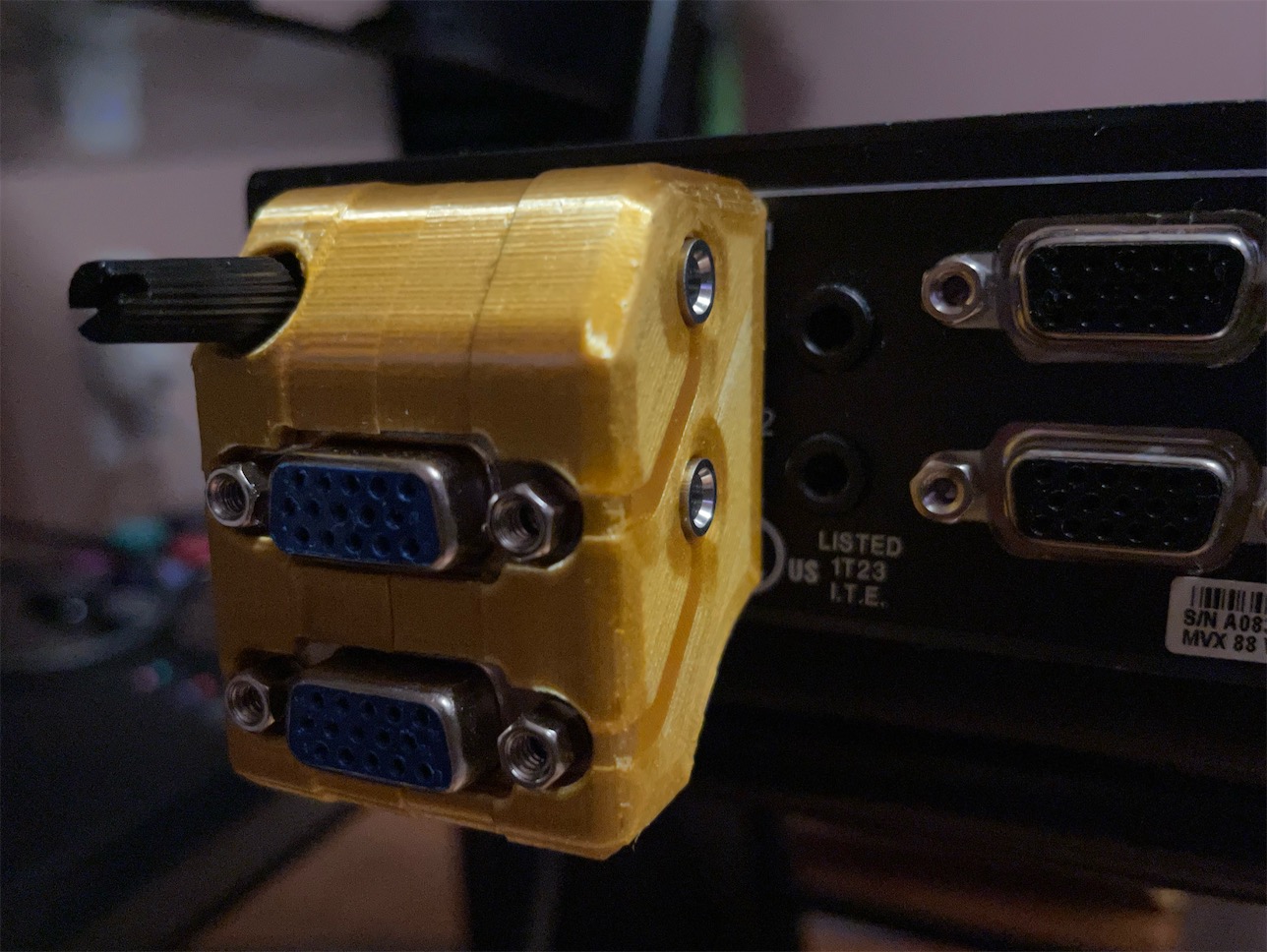
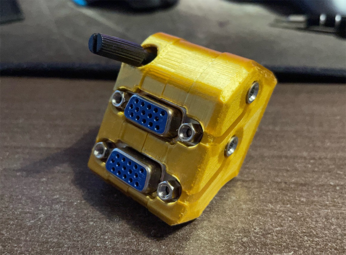
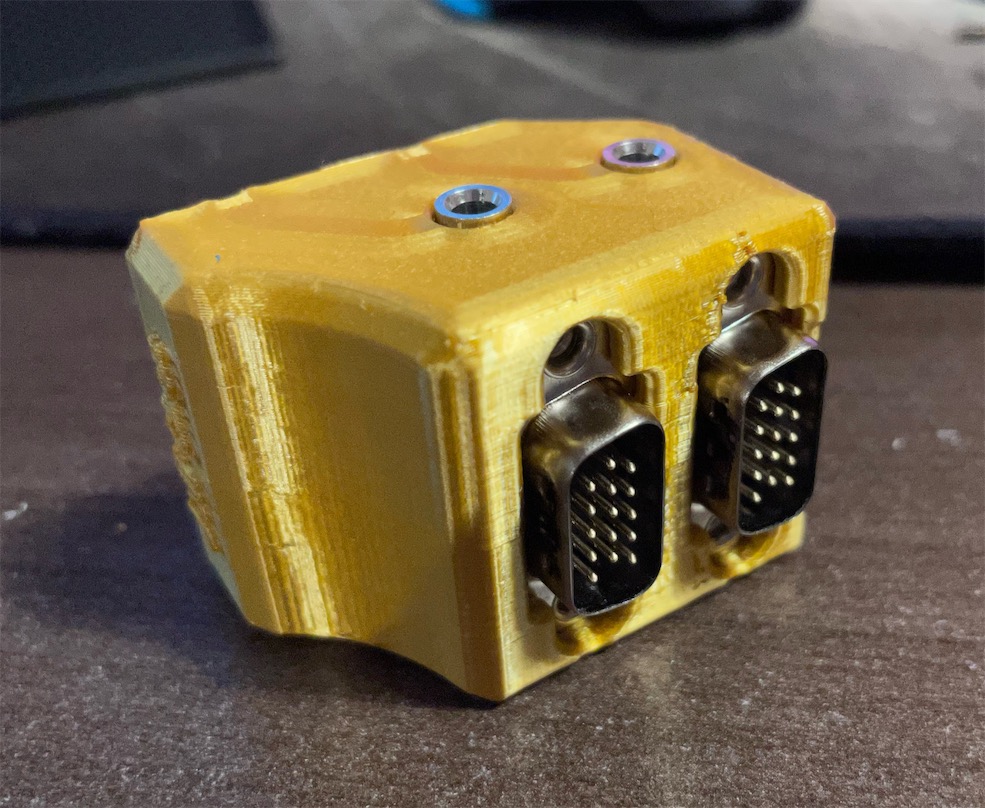
This is a dongle for separating and combining audio from/into VGA pin 12 and 15 and output from a 3.5mm jack, in order to interface with the Extron MVX VGA switch.
It's only necessary when you transmit audio through the VGA cable into/out of the Extron MVX switch.
Here are the necessary parts:
If you wish to break out the audio from the VGA cable at any time, you can make just ONE of these PCB and use it.
VGA Port Slim Female - Link
VGA Port Male Slim - Link
Vertical 3.5mm Headphone Jack - Link
[2x] M3x20mm screw & nut - Link
VGA Thumb Screw - Link
3.5mm Audio Jumper Cable - Link
3D Printed Shells
Solder the VGA ports according to the silk screen print. Make sure the ports sit tightly on top of the PCB. Solder two copies of the PCB assembly. Make sure to trim the extra length of the pins of the audio jack for the upper assembly, or it will interfere with the bottom assembly.
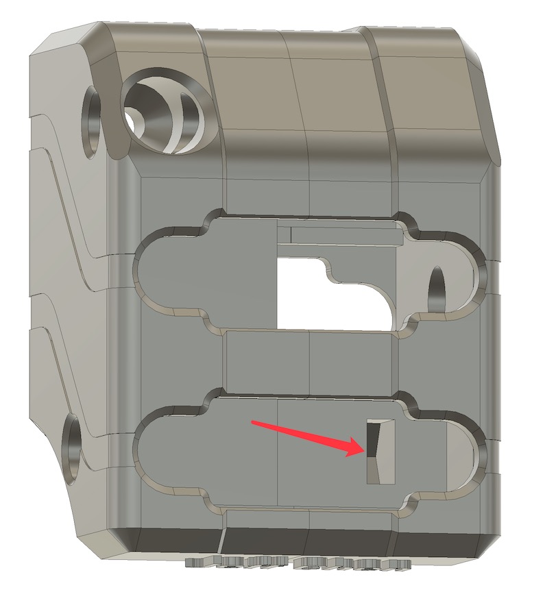
Insert two nuts into the slot inside the right shell
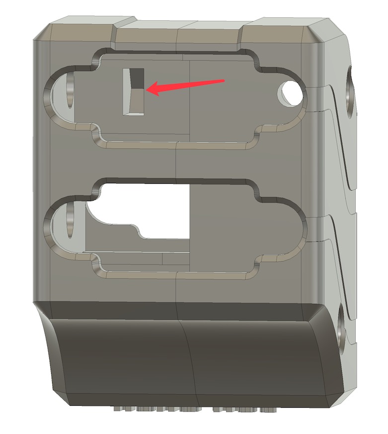
Insert the two PCB assembly into the right shell
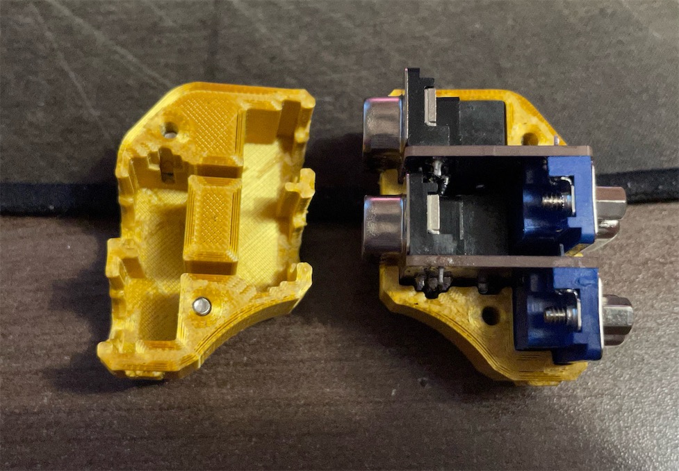
Close the left shell onto the right. Then screw in the two M3x20 screws. Do not over tighten the screws, or the nuts would break free inside the slots.
Last, screw in the thumb screw.
Due to the space restriction behind the MVX switch, you will need a audio jumper cable with both ends in a right angle for clearance. Here is an example:
Shield: 
This work is licensed under a Creative Commons Attribution-ShareAlike 4.0 International License.

| Qty | Value | Footprint | References |
|---|---|---|---|
| 1 | 3.5mm_vertical | MVX_Audio_Separator:3.5mm_Vertical | J1 |
| 1 | LOGO | MVX_Audio_Separator:PCB_outline | G*** |
| 1 | VGA_Female | MVX_Audio_Separator:VGA_female_rightangle_slim | P1 |
| 1 | VGA_Male | MVX_Audio_Separator:VGA_male_rightangle_slim | P2 |
joypad-ai/joypad-os
Universal controller firmware for building adapters, dongles, and custom controllers.


hackclub/OnBoard
💡 Join 1,000 teenagers and make your first PCB with a $100 grant!

tardate/LittleArduinoProjects
a collection of "Little Electronic & Arduino Projects", most involving electronics or an Arduino in one way or another!

drandyhaas/KiCadRoutingTools
A set of Python/Rust tools to aid routing in KiCad

osy/XG_Mobile_Station
Open source eGPU dock for ROG Ally and ROG Flow

Luos-io/luos_engine
Open-source and real-time orchestrator for cyber-physical-systems, to easily design, test and deploy embedded applications and digital twins.

NVNTLabs/switch2-SDEX2M2
Micro SD Express to M.2 NVME Adapter for Nintendo Switch 2
It measures 30.8 × 26.8 mm and has 2 copper layers, 1.6 mm thick.
4 parts. The full list of its parts is on this page, with links to each part's symbol and footprint where PCBKit's library has them.
From the jeffqchen/MVX-Audio-Separator-Combiner repository on GitHub, at the commit this page was made from: the board is KiCAD/MVX_Audio_Separator/MVX_Audio_Separator.kicad_pcb. PCBKit opens the board in the browser, with nothing to install.
Its repository publishes it under the CC-BY-SA-4.0 licence: you may reuse it on that licence's terms (keep the author's notice, and for a copyleft licence share your changes alike).