2 layers143.5 × 115.5 mm
SofleKeyboard
josefadamcik/SofleKeyboard
A split keyboard based on Lily58, Crkbd and Helix keyboards
89 parts2.6k

 jeffdhooton/jingis387
38-key ergonomic keyboard
Thesplit is an open-source printed circuit board by jeffdhooton, from the jeffdhooton/jingis38 repository on GitHub. It is a 2-layer board of 298.2 × 123.3 mm with 89 parts on 60 nets, routed with 854 tracks and 10 vias.
Its parts include 38 diodes and 38 switches. It belongs with the keyboards and input boards of this library.
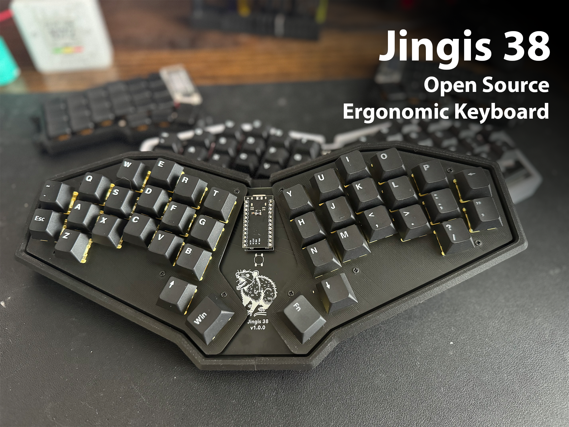
This is an ergonomic, 38-key, VIAL compatible keyboard based off of the corne/crkbd but with a larger column stagger. I designed the board to be hotswap, and use cheap SMD components, and a 3D printed case.
You will need all of the following to build one of these boards.
PCBs from a PCB manufacturer (JLCPCB cost me $18 for 5 of these boards)
Pro Micro ATMega32U4
1N1418 SMD Diodes
Kailh Hotswap Sockets
MX Keyswitches
MX Keycaps
M2 Heatset Inserts
M2x10 standoff screws
CA Glue
Once you receive your PCBs in, and have all of your components - you're ready to build. Building this board should be pretty straight forward for anybody that's done so for other boards before. If you haven't, then the build process is as follows:
Solder SMD components
The first step is to tin one side of the pads for every diode spot on the board. Once you have tinned the pads, you're ready to solder the components on. Make sure that you're soldering diodes on with the correct polarity. Diodes should have a line on one side of them, so make sure this lines up with the point of the triangle on the PCB. If you solder them on backwards, you're going to have a bad time.
Kailh hotswap sockets should come second. My process for soldering these is similar to the diodes - tin one of the pads for every spot on the board, solder the component to the tinned pad and then when done with the whole board, come back and add solder to the other pad, completing the connection
Solder Pro Micro
The next step is to solder on the MCU headers. The MCU on this board goes on top of the board. Place the header pins through the top of the board and solder on the back. Tack one pin on for each side and then ensure that the headers are vertical in their slots and not leaning to one side or the other.
After you've got the headers attached to the board you can solder the MCU to the headers. The MCU for this board should be upside down, with the USB-C port facing the board instead of facing away from the board.
Prepare Case for Install
The case prints in 4 pieces. Two halves and then two switch plates. There are also butterfly mechanisms on the build plate for connecting the two halves of the case. Align the two halves of the case, put some super glue in the butterfly slots on the case and then put the joiners in those slots.
When the glue sets, install heatset inserts into every standoff hole in the case. These should be M2 standoffs so that you can get screws through the holes on the PCB.
Install Switches & Assemble Board
Place the switches into the plates that you've printed off, and then line the plates up against the board and press down. Make sure you don't bend any switch pins during this process.
When you have switches on each side attached to the board via the hotswap sockets place the completed PCB into the case. Use M2x10 standoff screws through the holes on the switch plates to attach the board to the case. When you've got them all added the board should feel secure.
Flash Firmware
Check out the readme in the jingis directory of this repository for instructions on how to flash the firmware.
| Qty | Value | Footprint | References |
|---|---|---|---|
| 38 | MX | S1, S2, S10, S11, S12, S13, S14, S15, S16, S17, S18, S19, S20, S21, S22, S23 +22 | |
| 38 | ComboDiode | D1, D2, D10, D11, D12, D13, D14, D15, D16, D17, D18, D19, D20, D21, D22, D23 +22 | |
| 10 | MountingHole_2.2mm_M2_Pad_Via | _1, _2, _3, _4, _5, _6, _7, _8, _9, _10 | |
| 1 | E73:SW_TACT_ALPS_SKQGABE010 | B1 | |
| 1 | ProMicro | MCU1 | |
| 1 | LOGO | myboard:pcb-graphic-2 | G*** |
josefadamcik/SofleKeyboard
A split keyboard based on Lily58, Crkbd and Helix keyboards


tebl/BulkyMIDI-32
A HW build of the MT32-PI project, allowing you to emulate a Roland MT-32 using a Raspberry Pi. Includes enough additional modules to build a MIDI-mountain as well as adapters for connecting to most things retro.
It measures 298.2 × 123.3 mm and has 2 copper layers, 1.6 mm thick.
89 parts. The full list of its parts is on this page, with links to each part's symbol and footprint where PCBKit's library has them.
From the jeffdhooton/jingis38 repository on GitHub, at the commit this page was made from: the board is kicad/jingis38/thesplit.kicad_pcb and its schematic kicad/jingis38/thesplit.kicad_sch. PCBKit opens the board in the browser, with nothing to install.
Its repository states no licence, so its author keeps all rights: ask jeffdhooton before reusing the design.