2 layers18.5 × 11.1 mm
Switch
byrantech/laptop
anyon_e, a highly integrated, high end, open source laptop. Attempt the impossible.
6 parts4.3kMIT

 jedp/RGB-5050-2
Chainable board for mounting RBG-5050 LEDs
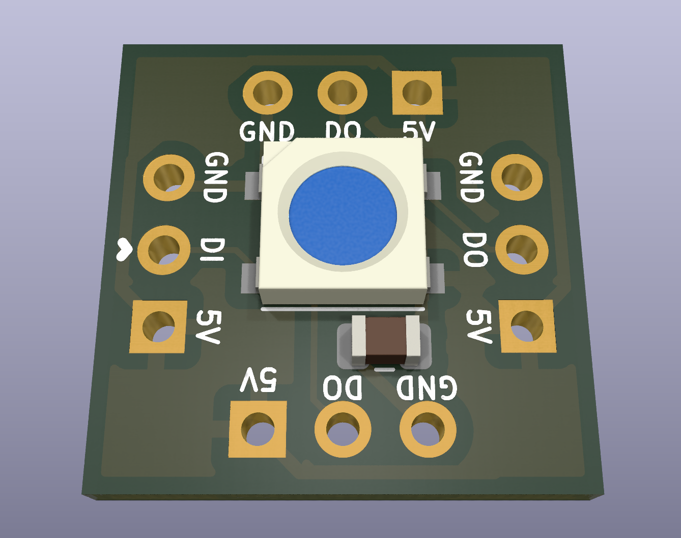
RGB-5050-2 is an open-source printed circuit board by jedp, from the jedp/RGB-5050-2 repository on GitHub. It is a 2-layer board of 15.2 × 15.2 mm with 6 parts on 4 nets, routed with 39 tracks and 0 vias.
Its parts include 4 connectors and 1 capacitor. It belongs with the lEDs and displays boards of this library.
A chainable board for mounting addressable RGB 5050 LEDs to things.
These high-speed LEDs deal in ones and zeros at microsecond speed. One way to get this kind of speed out of an STM32 without tying up the CPU and/or writing a lot of custom assembly is to use SPI to transmit the data, possibly using DMA to send the data to SPI.
The RGB5050 encodes 0 and 1 values as high/low transitions like so:
0 -> 0.3µs high ± 0.15µs, 0.9µs low ± 0.15µs
1 -> 0.6µs high ± 0.15µs, 0.6µs low ± 0.15µs
My first attempt was to try a transfer rate of 2.5Mbps, since this would require the minimum number of encoded output bits (0 -> 0b100, 1 -> 0b110). This is obviously out of spec for the timings. It was worth a go, bit it didn't work reliably.
Bumping the transfer rate to 5Mbps doubles the number of bits required, but has the benefit of actually working:
0 -> 0b100000 (0.2µs high, 1.0µs low)
1 -> 0b111000 (0.6µs high, 0.6µs low)
To implement this, one could iterate over each source byte of and do some fancy bit arithmetic for every single byte (see previous commit), or one could follow the advice of the mighty Ross Glashan and just use a lookup table, since there are only 16 possible encodings of each nibble.
For example:
static uint32_t color_nibbles[16] = {
		0x820820, // 0b0000 -> 0b100000100000100000100000
		0x820838, // 0b0001 -> 0b100000100000100000111000
		0x820e20, // 0b0010 -> 0b100000100000111000100000
		0x820e38, // etc.
		0x838820,
		0x838838,
		0x838e20,
		0x838e38,
		0xe20820,
		0xe20838,
		0xe20e20,
		0xe20e38,
		0xe38820,
		0xe38838,
		0xe38e20,
		0xe38e38, // 0b1111 -> 0b111000111000111000111000
};

/*
 * Convert the pixel represented by (r, g, b), using the scheme described
 * at the head of this file, and pack it into buf in RGB 5050 order:
 * G, R, B; MSB first.
*/So you could set a region of a buffer like this:
RGB5050_pixel_write(0xAB, 0xCD, 0xEF, (uint8_t*) (some_buffer + 18 * offset));And then transmit that buffer over SPI:
HAL_SPI_Transmit(&hspi1, (uint8_t*) some_buffer, sizeof(some_buffer), 1);After transmission, leave a reset cycle of at least 80µs before transmitting again.
| Qty | Value | Footprint | References |
|---|---|---|---|
| 4 | Conn_01x03_Female | Connector_PinHeader_2.54mm:PinHeader_1x03_P2.54mm_Vertical | J1, J2, J3, J4 |
| 1 | 0.1uF | Capacitor_SMD:C_0805_2012Metric | C1 |
| 1 | Inolux_IN-PI554FCH | LED_SMD:LED_Inolux_IN-PI554FCH_PLCC4_5.0x5.0mm_P3.2mm | RGB_1 |
byrantech/laptop
anyon_e, a highly integrated, high end, open source laptop. Attempt the impossible.


Jcparkyn/dpoint
Open-source digital stylus using camera tracking and inertial measurements

VoronDesign/Voron-Hardware
Cool Hardware designed by the Voron Design group

hoglet67/RGBtoHDMI
Bare-metal Raspberry Pi project that provides pixel-perfect sampling of Retro Computer RGB/YUV video and conversion to HDMI

hackclub/OnBoard
💡 Join 1,000 teenagers and make your first PCB with a $100 grant!

Luos-io/luos_engine
Open-source and real-time orchestrator for cyber-physical-systems, to easily design, test and deploy embedded applications and digital twins.

It measures 15.2 × 15.2 mm and has 2 copper layers, 1.6 mm thick.
6 parts. The full list of its parts is on this page, with links to each part's symbol and footprint where PCBKit's library has them.
From the jedp/RGB-5050-2 repository on GitHub, at the commit this page was made from: the board is kicad/RGB_5050.2.kicad_pcb and its schematic kicad/RGB_5050.2.kicad_sch. PCBKit opens the board in the browser, with nothing to install.
Its repository states no licence, so its author keeps all rights: ask jedp before reusing the design.