4 layers85 × 56 mm

 jblang/avrbrain1
An AVR128DB64 development board
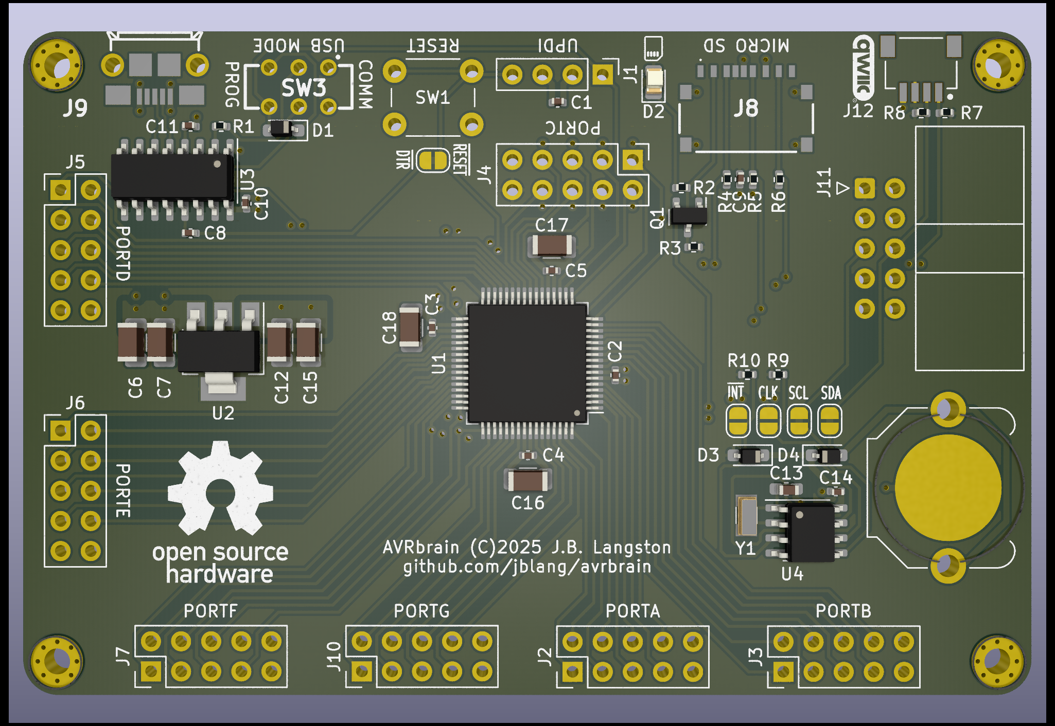
Avrbrain is an open-source printed circuit board by jblang, from the jblang/avrbrain repository on GitHub, published under the MIT licence. It is a 4-layer board of 85 × 56 mm with 64 parts on 94 nets, routed with 699 tracks and 91 vias.
It is built around the CH340C, XKTF-0803-0 and AMS1117-3.3, with the PCF8563T/5, 1N5819WS and BSS138 among its other parts. Its parts include 19 capacitors, 12 connectors, 10 resistors, 4 ICs and 4 diodes. It belongs with the microcontroller boards boards of this library.


AVRbrain is an AVR128DB64 dev board. The AVR Dx series are modern AVRs with many desireable features over the classic ATmega AVRs, such as multi-voltage I/O, configurable logic, advanced analog features, and a single-wire programming and debug interface.
AVRbrain is compatible with the DxCore Arduino Core. I have tested the AVR128DB28 on a breadboard with the same programming circuit I intend to use on the finished board, and confirmed that it works.
Once flashed in UPDI programming mode, the Optiboot_Dx bootloader can be used to reprogram the board in serial comms mode, and there is an auto-reset circuit connected to the DTR line (possible to disable with a jumper).
AVRbrain is compatible with PlatformIO using the Atmel megaAVR platform. PlatformIO supports Arduino development using DxCore, or native development using avr-libc.
Here's the platformio.ini that I used to build a simple non-Arduino led blinking example for the AVR128DB64:
[env:AVR128DB28]
platform = atmelmegaavr
platform_packages = platformio/toolchain-atmelavr@^3.70300.220127
board = AVR128DB28
upload_speed = 115200
upload_flags =
    --tool
    uart
    --device
    avr128db28
    --uart
    $UPLOAD_PORT
    --clk
    $UPLOAD_SPEED
upload_command = pymcuprog write --erase $UPLOAD_FLAGS --filename $SOURCE
The above example can be made to work with DxCore just by adding the line framework = arduino to this file.
z80ctrl NG is the next-generation z80ctrl board I am designing concurrently with AVRbrain. It uses all the same hardware components, including the AVR128DB64, the USB chip, RTC, voltage regulator, sd card slot, etc. The primary difference is the pinout. The z80ctrl NG is intended to interface with the RCBus parallel bus used primarily by Z80-based retrocomputers, whereas AVRbrain is intended as a general-purpose dev board with stacking shield-style modules or IDC cables. z80ctrl also includes a 512K SRAM chip with optional banking that can be initialized by the AVR and then used by the 8-bit processor that z80ctrl shares a bus with.
| Qty | Value | Footprint | References |
|---|---|---|---|
| 10 | 0.1uf | Capacitor_SMD:C_0402_1005Metric | C1, C2, C3, C4, C5, C8, C9, C10, C11, C14 |
| 4 | 100K | Resistor_SMD:R_0402_1005Metric | R3, R4, R5, R6 |
| 4 | 1uf | Capacitor_SMD:C_0402_1005Metric | C16, C17, C18, C19 |
| 4 | 2.2K | Resistor_SMD:R_0402_1005Metric | R7, R8, R9, R10 |
| 4 | MountingHole_Pad | MountingHole:MountingHole_2.2mm_M2_Pad_Via | H1, H2, H3, H4 |
| 3 | 1N5819WS | Diode_SMD:D_SOD-323 | D1, D3, D4 |
| 2 | 1K | Resistor_SMD:R_0402_1005Metric | R1, R2 |
| 2 | 1uf | Capacitor_SMD:C_1206_3216Metric | C7, C12 |
| 2 | 22uf | Capacitor_SMD:C_1206_3216Metric | C6, C15 |
| 1 | 27pf | Capacitor_SMD:C_0603_1608Metric | C13 |
| 1 | 32kHz | Crystal:Crystal_SMD_3215-2Pin_3.2x1.5mm | Y1 |
| 1 | AMS1117-3.3 | Package_TO_SOT_SMD:SOT-223-3_TabPin2 | U2 |
| 1 | AUTORESET | Jumper:SolderJumper-2_P1.3mm_Bridged_RoundedPad1.0x1.5mm | JP1 |
| 1 | AVR128DB64x-xPT | Package_QFP:TQFP-64_10x10mm_P0.5mm | U1 |
| 1 | BSS138 | Package_TO_SOT_SMD:SOT-23 | Q1 |
| 1 | CH340C | Package_SO:SOIC-16_3.9x9.9mm_P1.27mm | U3 |
| 1 | CR1216 | Battery:BatteryHolder_Keystone_3001_1x12mm | BT1 |
| 1 | LED | LED_SMD:LED_0603_1608Metric | D2 |
| 1 | NetTie_2 | NetTie:NetTie-2_SMD_Pad0.5mm | NT1 |
| 1 | PCF8563T | Package_SO:SOIC-8_3.9x4.9mm_P1.27mm | U4 |
| 1 | PORTA | Connector_PinHeader_2.54mm:PinHeader_2x05_P2.54mm_Vertical | J2 |
| 1 | PORTB | Connector_PinHeader_2.54mm:PinHeader_2x05_P2.54mm_Vertical | J3 |
| 1 | PORTC | Connector_PinHeader_2.54mm:PinHeader_2x05_P2.54mm_Vertical | J4 |
| 1 | PORTD | Connector_PinHeader_2.54mm:PinHeader_2x05_P2.54mm_Vertical | J5 |
| 1 | PORTE | Connector_PinHeader_2.54mm:PinHeader_2x05_P2.54mm_Vertical | J6 |
| 1 | PORTF | Connector_PinHeader_2.54mm:PinHeader_2x05_P2.54mm_Vertical | J7 |
| 1 | PORTG | Connector_PinHeader_2.54mm:PinHeader_2x05_P2.54mm_Vertical | J10 |
| 1 | PROG_EN | SamacSys_Parts:JS202011CQN | SW3 |
| 1 | RESET | Button_Switch_THT:SW_PUSH_6mm | SW1 |
| 1 | RTC_CLK | Jumper:SolderJumper-2_P1.3mm_Open_RoundedPad1.0x1.5mm | JP6 |
| 1 | RTC_INT | Jumper:SolderJumper-2_P1.3mm_Open_RoundedPad1.0x1.5mm | JP7 |
| 1 | RTC_SCL | Jumper:SolderJumper-2_P1.3mm_Bridged_RoundedPad1.0x1.5mm | JP2 |
| 1 | RTC_SDA | Jumper:SolderJumper-2_P1.3mm_Bridged_RoundedPad1.0x1.5mm | JP3 |
| 1 | SM04B-SRSS-TB | SamacSys_Parts:SM04B-SRSS-TB_LFSN_ | J12 |
| 1 | U254-051T-4BH81-S2S | SamacSys_Parts:U254051T4BH81S2S | J9 |
| 1 | UEXT | Connector_IDC:IDC-Header_2x05_P2.54mm_Horizontal | J11 |
| 1 | UPDI | Connector_PinHeader_2.54mm:PinHeader_1x04_P2.54mm_Vertical | J1 |
| 1 | XKTF-0803-0 | SamacSys_Parts:XKTF08030 | J8 |


LeeSpo/portable-display-epass-EVT1-minboot-r1
当前自研硬件为 38 × 64 mm、四层 split-power 工程候选,尚未放行生产。


SkullKill/ESP32-Wall-Clock-PCB
ESP32 based 30cm Wall Mounted Clock. WiFi, NTP, SNMP, web interface, MicroUsb, Type-C, HG3613 Retrofit

NarodniySputnik/Gladiolus-1
Gladiolus-1 - автономный модуль для приема и передачи изображений в формате SSTV (Slow Scan TeleVision) на малом космическом аппарате (МКА) формата CubeSat

yussufadel8/BLDC-Motor-Controller-STM32
Two-layer 3-phase BLDC controller in KiCad — STM32G431 FOC MCU with on-board STM32F103 SWD debugger, IR2104 half-bridges, and 3-shunt current sensing via the G431's internal op-amps.


rh1tech/frank-lab
FRANK Board Laboratory (work-in-progress board prototopyes)
It measures 85 × 56 mm and has 4 copper layers, 1.6 mm thick.
64 parts, built around the CH340C, XKTF-0803-0, AMS1117-3.3 and PCF8563T/5. The full list of its parts is on this page, with links to each part's symbol and footprint where PCBKit's library has them.
From the jblang/avrbrain repository on GitHub, at the commit this page was made from: the board is avrbrain.kicad_pcb and its schematic avrbrain.kicad_sch. PCBKit opens the board in the browser, with nothing to install.
Its repository publishes it under the MIT licence: you may reuse it on that licence's terms (keep the author's notice, and for a copyleft licence share your changes alike).

