

4 layers101.6 × 141.7 mm
 jbazant/esp8266-binary-clock
Private home decor project.
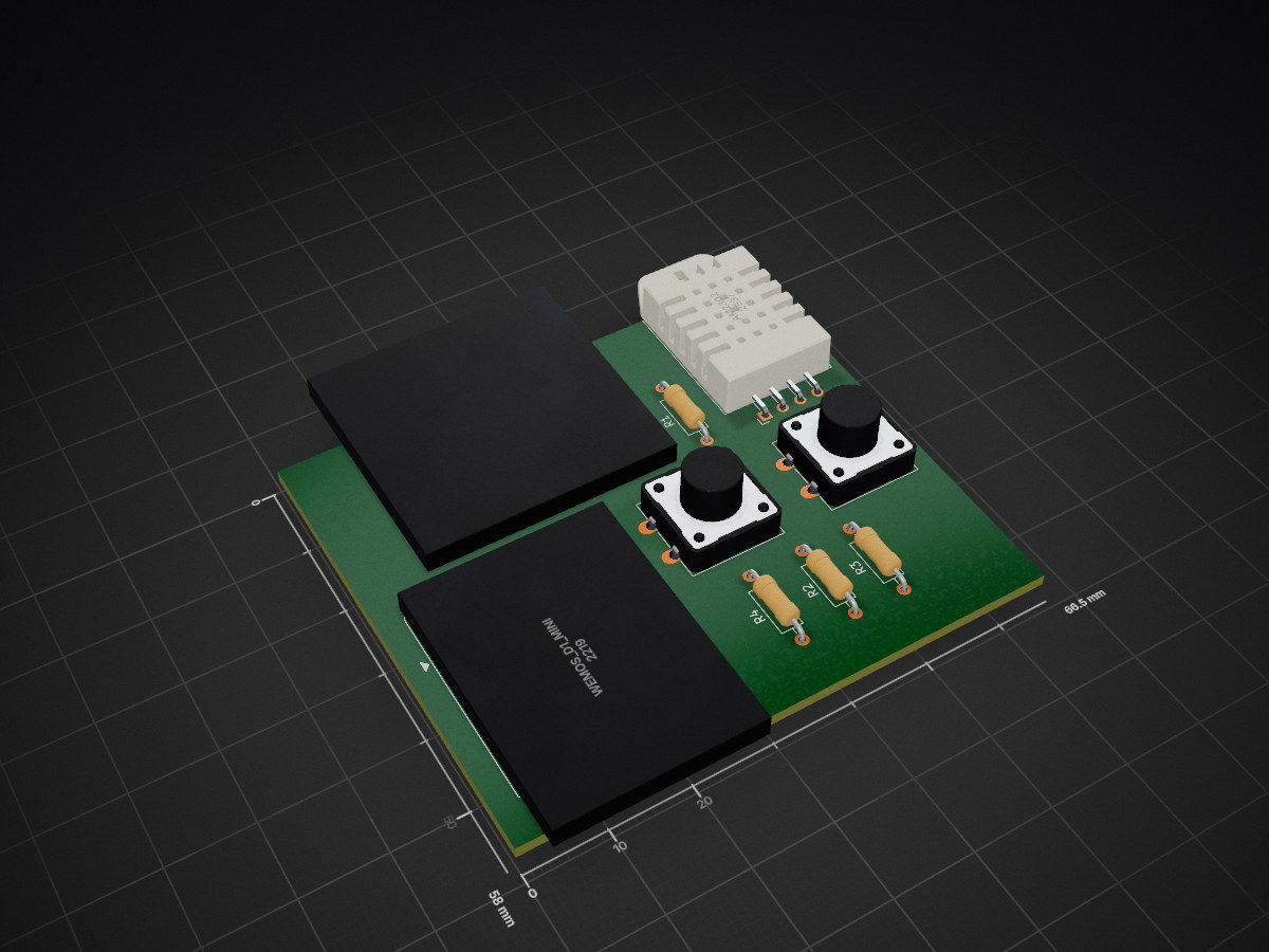
Binary clock is an open-source printed circuit board by jbazant, from the jbazant/esp8266-binary-clock repository on GitHub, published under the MIT licence. It is a 2-layer board of 66.5 × 58 mm with 9 parts on 17 nets, routed with 106 tracks and 0 vias.
It is built around the WEMOS D1 MINI and AM2302. Its parts include 4 resistors, 3 ICs and 2 switches. It belongs with the lEDs and displays boards and the ESP8266 boards of this library.
This is a private project. No support is provided. No input expected. Also as soon as I finish 1st version, I will probably not work on it anymore.
Esp8266 based, IKEA Skadis mounted, NTP synchronized, "smart" binary clock with temperature and humidity sensor.
Binary clock based on a WEMOS D1 mini and a 8x8 LED matrix. Shows the seconds, minutes, hours, day in month, day in week, month, lunar phase and last two decimal digits of year in binary format. Also uses a DHT sensor to show the temperature and humidity. Time is synchronized via NTP.
Two buttons allow to disable display and set the brightness.

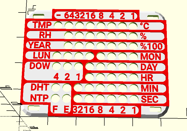
Rows from top to bottom:
| Bits 5 - 8 | Lunar phase | 🌝 |
|---|---|---|
| 0000 | New moon | 🌑 |
| 0001 | Waxing crescent | 🌒 |
| 0011 | First quarter | 🌓 |
| 0111 | Waxing gibbous | 🌔 |
| 1111 | Full moon | 🌕 |
| 1110 | Waning gibbous | 🌖 |
| 1100 | Last quarter | 🌗 |
| 1000 | Waning crescent | 🌘 |
Photo of the clock shows: Wednesday, 18th of September 2024, 12:17:35, full moon, 28°C, 52% relative humidity.
The software is written as arduino project mostly in C++ and can be found in the esp8266-binary-clock folder (to
satisfy arduino project structure).
secrets.h in the esp8266-binary-clock and specify your WiFi credentials. (see secrets.h.example)CONFIGURATION section and initTimezoneAndDST method in esp8266-binary-clock.ino to your needs (or just
leave as is).
DHT_INTERVAL_S - interval for reading DHT sensor (in seconds), default 1 minuteNTP_INTERVAL_S - interval for NTP synchronization (in seconds), default 12 hoursThe PCB is designed in KiCad and can be found in the pcb folder. Size of the PCB board is 66 x58 mm with LED matrix
and DHT22 sensor overhanging the board.
Board is actually pretty simple and uses just one Cu layer and 0.5mm clearance between tracks. You need to use 1.6mm PCB
thickness or adjust the case (bottom part).
The case is designed in OpenScad and can be found in the case folder. Optimized (well as much as I was able to...) for
FDM 3D printing.
Case is divided into 3 parts:
case_bottom.scad)case_top.scad)display_plate.scad)One can render all parts with the case.scad file.
All the parts should snap together without any screws or glue.
Case is printed with supports that are included in the model. Do not add supports in slicer! After printing, remove the "triangle" simply by tilting it back and forth and "mouse ears" with a knife.
Assembled PCB (optimized for 1.6mm height) should fit into the model without any screws or glue. Some force is needed to snap it in.
| Qty | Value | Footprint | References |
|---|---|---|---|
| 2 | 10K | Resistor_THT:R_Axial_DIN0207_L6.3mm_D2.5mm_P10.16mm_Horizontal | R2, R3 |
| 2 | 10k | Resistor_THT:R_Axial_DIN0207_L6.3mm_D2.5mm_P10.16mm_Horizontal | R1, R4 |
| 1 | AM2302 | Sensor:ASAIR_AM2302_P2.54mm_Lead2.75mm_TabDown | U2 |
| 1 | Intensity | Button_Switch_THT:SW_PUSH-12mm | SW2 |
| 1 | On/Off | Button_Switch_THT:SW_PUSH-12mm | SW1 |
| 1 | WeMos_D1_mini | Module:WEMOS_D1_mini_light | U1 |
| 1 | ~ | LED_THT:FC-16 | U3 |
It measures 66.5 × 58 mm and has 2 copper layers, 1.6 mm thick.
9 parts, built around the WEMOS D1 MINI and AM2302. The full list of its parts is on this page, with links to each part's symbol and footprint where PCBKit's library has them.
From the jbazant/esp8266-binary-clock repository on GitHub, at the commit this page was made from: the board is pcb/binary-clock.kicad_pcb and its schematic pcb/binary-clock.kicad_sch. PCBKit opens the board in the browser, with nothing to install.
Its repository publishes it under the MIT licence: you may reuse it on that licence's terms (keep the author's notice, and for a copyleft licence share your changes alike).

OpenHumidistat/hardware
KiCAD design files for PCBs for the OpenHumidistat humidity controller

tjiuce/rover
Rover Navigation Optimization System (R-NOS): An ESP32-powered autonomous robotic prototype designed for real-time environmental monitoring.

Launchpad-Incubator/weather-balloon
The research repository for Launchpad's flat-packed weather balloons.

Aanuoluwap/555blinker
This repository contains electronics design projects created using KiCad.

pasinduh2002/GasGuard
IoT and ML-based LPG monitoring system with ESP32 leak detection, automatic valve shutoff, real-time mobile alerts and refill prediction. Built with React Native, Firebase and Python.

