
2 layers80 × 49 mm
Obd2
kevinkrieger/CAN
CAN repository containing my CAN project, kicad files, firmware, datasheets, references, etc.
64 parts3

 jasminpatry/boostino16
A Teensy 3.6-based logger and gauge for my 2014 Subaru STI.
Boostino is an open-source printed circuit board by jasminpatry, from the jasminpatry/boostino repository on GitHub, published under the GPL-3.0 licence. It is a 2-layer board of 87.6 × 50.8 mm with 22 parts on 70 nets, routed with 188 tracks and 15 vias.
It is built around the MC33660BEF. Its parts include 7 resistors, 3 capacitors, 3 diodes, 2 ICs and 2 connectors. It belongs with the NXP (LPC, Kinetis, i.MX RT) boards of this library.
A Teensy 3.6-based logger and gauge for my 2014 Subaru STI.
Photo of current version:

Short YouTube video of older version, without faceplate or wideband support:
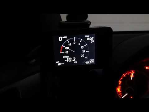
See this thread on NASIOC for more info.
This project is built as an Arduino sketch. I used Arduino 1.8.8, but later versions will likely work too. You will also need the Teensyduino add-on (https://www.pjrc.com/teensy/td_download.html), and the following libraries:
This project was built using the following hardware:
A previous version of this project used the Tactrix OpenPort 2.0 to communicate with the ECU. That version is available in the Tactrix branch.
If this project proves useful to you, please consider making a donation!

| Qty | Value | Footprint | References |
|---|---|---|---|
| 4 | MountingHole_3.2mm_M3 | MountingHole:MountingHole_3.2mm_M3 | , , , |
| 2 | 2.2K | Resistor_SMD:R_0805_2012Metric_Pad1.15x1.40mm_HandSolder | R1, R3 |
| 2 | 3.3K | Resistor_SMD:R_0805_2012Metric_Pad1.15x1.40mm_HandSolder | R2, R4 |
| 1 | 10K | Resistor_SMD:R_0805_2012Metric_Pad1.15x1.40mm_HandSolder | R5 |
| 1 | 10nF | Capacitor_SMD:C_1206_3216Metric_Pad1.42x1.75mm_HandSolder | C3 |
| 1 | 1nF | Capacitor_SMD:C_1206_3216Metric_Pad1.42x1.75mm_HandSolder | C1 |
| 1 | 2N3904 | Package_TO_SOT_THT:TO-92_HandSolder | Q1 |
| 1 | 500 | Resistor_SMD:R_0805_2012Metric_Pad1.15x1.40mm_HandSolder | R7 |
| 1 | 510 | Resistor_SMD:R_0805_2012Metric_Pad1.15x1.40mm_HandSolder | R6 |
| 1 | 5nF | Capacitor_SMD:C_1206_3216Metric_Pad1.42x1.75mm_HandSolder | C2 |
| 1 | Conn_01x04_Male | Connector_PinHeader_2.54mm:PinHeader_1x06_P2.54mm_Horizontal | J2 |
| 1 | Conn_01x14_Female | Connector_PinSocket_2.54mm:PinSocket_1x14_P2.54mm_Vertical | J1 |
| 1 | D | Diode_THT:D_A-405_P10.16mm_Horizontal | D1 |
| 1 | D_Zener_27V | Diode_SMD:D_MiniMELF_Handsoldering | D2 |
| 1 | D_Zener_45V | Diode_SMD:D_MiniMELF_Handsoldering | D3 |
| 1 | MC33660 | Package_SO:SOIC-8_3.9x4.9mm_P1.27mm | U2 |
| 1 | Teensy3.6 | Teensy:Teensy35_36 | U1 |
It measures 87.6 × 50.8 mm and has 2 copper layers, 1.6 mm thick.
22 parts, built around the MC33660BEF. The full list of its parts is on this page, with links to each part's symbol and footprint where PCBKit's library has them.
From the jasminpatry/boostino repository on GitHub, at the commit this page was made from: the board is KiCad/boostino.kicad_pcb. PCBKit opens the board in the browser, with nothing to install.
Its repository publishes it under the GPL-3.0 licence: you may reuse it on that licence's terms (keep the author's notice, and for a copyleft licence share your changes alike).
kevinkrieger/CAN
CAN repository containing my CAN project, kicad files, firmware, datasheets, references, etc.


VoronDesign/Voron-Hardware
Cool Hardware designed by the Voron Design group

hoglet67/RGBtoHDMI
Bare-metal Raspberry Pi project that provides pixel-perfect sampling of Retro Computer RGB/YUV video and conversion to HDMI

hackclub/OnBoard
💡 Join 1,000 teenagers and make your first PCB with a $100 grant!

abhishek-kakkar/BeagleLogic
A Software Suite that implements a logic analyzer with the PRU on the BeagleBone / BeagleBone Black.

Chrismettal/flipper-zero-backpacks
Backpack-style addon boards for the Flipper Zero!
