
2 layers50 × 25 mm
Mbus master
roarfred/AmsToMqttBridge
Minimalistic system to read AMS/HAN data from electrical meter
50 parts223

 JanBurp/MorphaLogic9
An eurorack logic module with several logic functions and a clock divider mode. Build around an arduino nano. So could be reprogrammed.
LogicModule is an open-source printed circuit board by JanBurp, from the JanBurp/MorphaLogic repository on GitHub. It is a 2-layer board of 29.2 × 110.1 mm with 59 parts on 58 nets, routed with 337 tracks and 0 vias.
It is built around the BC337. Its parts include 23 resistors, 17 diodes, 11 connectors, 4 transistors and 3 switches. It belongs with the audio and music and lEDs and displays boards and the AVR (ATmega, ATtiny) boards of this library.
An Eurorack module based around a Arduino Nano.
With AND, OR, XOR logic functions, a Flip Flip (Q), a Clock Divider mode, and more.
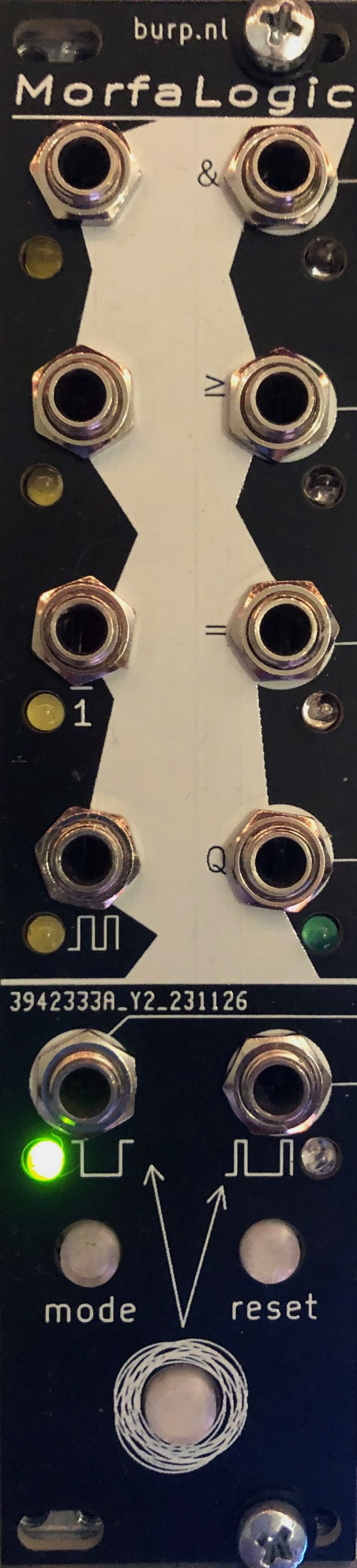
| LEFT | RIGHT |
| INPUT: input (A) | OUTPUT: AND (or clock / 16) |
| INPUT: input (B) | OUTPUT: OR (or clock / 8) |
| INPUT: Inverse (INV) | OUTPUT: XOR (or clock / 4) |
| INPUT: Clock (CLK) | OUTPUT: Q - Flip Flop (or clock / 2) |
| OUTPUT: Inverse of TRIG BUTTON | Trigger on press & release of TRIG BUTTON |
| BUTTON: Mode button | BUTTON: Reset button |
| TRIG BUTTON | |
When the TRIG button is pressed (and released):
Current mode is set in memory.
One of my main modules in my eurorack case is the Make-Noise Morphagene. One thing that i'd like it to do is:
To make this work:
Record option (rsop) in the options.txt file on the SD card to '1'.Now:
In this repo you'll find:
If you'd like to build this module you can buy a kit with:
Contact me if you are interested.
By Jan den Besten www.jandenbesten.com
| Qty | Value | Footprint | References |
|---|---|---|---|
| 12 | 1K | Resistor_THT:R_Axial_DIN0207_L6.3mm_D2.5mm_P10.16mm_Horizontal | R6, R8, R10, R11, R12, R13, R15, R17, R18, R19, R21, R22 |
| 7 | 1k | Resistor_THT:R_Axial_DIN0207_L6.3mm_D2.5mm_P10.16mm_Horizontal | R1, R2, R3, R5, R9, R16, R23 |
| 4 | 10k | Resistor_THT:R_Axial_DIN0207_L6.3mm_D2.5mm_P10.16mm_Horizontal | R4, R7, R14, R20 |
| 4 | 1N4148 | Diode_THT:D_DO-35_SOD27_P7.62mm_Horizontal | D4, D7, D11, D15 |
| 4 | BC337 | Package_TO_SOT_THT:TO-92_Inline | Q1, Q2, Q3, Q4 |
| 1 | AND | Connector_Audio:Jack_3.5mm_QingPu_WQP-PJ398SM_Vertical_CircularHoles | J3 |
| 1 | Arduino_Nano_v2.x | Module:Arduino_Nano | A1 |
| 1 | Button | Button_Switch_THT:SW_PUSH_6mm | SW1 |
| 1 | Conn_02x05_Odd_Even | Connector_PinHeader_2.54mm:PinHeader_2x05_P2.54mm_Vertical | J11 |
| 1 | INPUT A | Connector_Audio:Jack_3.5mm_QingPu_WQP-PJ398SM_Vertical_CircularHoles | J1 |
| 1 | INPUT B | Connector_Audio:Jack_3.5mm_QingPu_WQP-PJ398SM_Vertical_CircularHoles | J2 |
| 1 | INPUT CLOCK | Connector_Audio:Jack_3.5mm_QingPu_WQP-PJ398SM_Vertical_CircularHoles | J9 |
| 1 | INPUT NOT | Connector_Audio:Jack_3.5mm_QingPu_WQP-PJ398SM_Vertical_CircularHoles | J6 |
| 1 | LED AND | LED_THT:LED_D3.0mm | D6 |
| 1 | LED Mode | LED_THT:LED_D3.0mm | D2 |
| 1 | LED OR | LED_THT:LED_D3.0mm | D9 |
| 1 | LED Q | LED_THT:LED_D3.0mm | D13 |
| 1 | LED Reset | LED_THT:LED_D3.0mm | D3 |
| 1 | LED XOR | LED_THT:LED_D3.0mm | D10 |
| 1 | LED button | LED_THT:LED_D3.0mm | D1 |
| 1 | LED inpA | LED_THT:LED_D3.0mm | D5 |
| 1 | LED inpB | LED_THT:LED_D3.0mm | D8 |
| 1 | LED inpCLK | LED_THT:LED_D3.0mm | D17 |
| 1 | LED inpNOT | LED_THT:LED_D3.0mm | D12 |
| 1 | LED ngate | LED_THT:LED_D3.0mm | D14 |
| 1 | LED trig | LED_THT:LED_D3.0mm | D16 |
| 1 | Mode | Button_Switch_THT:SW_PUSH_6mm | SW2 |
| 1 | NGATE | Connector_Audio:Jack_3.5mm_QingPu_WQP-PJ398SM_Vertical_CircularHoles | J8 |
| 1 | OR | Connector_Audio:Jack_3.5mm_QingPu_WQP-PJ398SM_Vertical_CircularHoles | J4 |
| 1 | Q | Connector_Audio:Jack_3.5mm_QingPu_WQP-PJ398SM_Vertical_CircularHoles | J7 |
| 1 | Reset | Button_Switch_THT:SW_PUSH_6mm | SW3 |
| 1 | TRIG | Connector_Audio:Jack_3.5mm_QingPu_WQP-PJ398SM_Vertical_CircularHoles | J10 |
| 1 | XOR | Connector_Audio:Jack_3.5mm_QingPu_WQP-PJ398SM_Vertical_CircularHoles | J5 |
It measures 29.2 × 110.1 mm and has 2 copper layers, 1.6 mm thick.
59 parts, built around the BC337. The full list of its parts is on this page, with links to each part's symbol and footprint where PCBKit's library has them.
From the JanBurp/MorphaLogic repository on GitHub, at the commit this page was made from: the board is kicad project/LogicModule.kicad_pcb and its schematic kicad project/LogicModule.kicad_sch. PCBKit opens the board in the browser, with nothing to install.
Its repository states no licence, so its author keeps all rights: ask JanBurp before reusing the design.
roarfred/AmsToMqttBridge
Minimalistic system to read AMS/HAN data from electrical meter


leomil72/LM80C
A Z80-based homebrew computer withTMS9918, AY-3-8910, Z80 CTC, Z80 PIO, and Z80 SIO

pablozg/freeds
Derivador de energía solar excedente creado por Pablo Zerón, Diseño PCB por Amcalo, Tester original por Aeizoon, Wiki por Zoilo Mora

lampmerchant/tashtwenty
An interface for the DCD protocol used by Apple's Hard Disk 20.

CTXz/Video-Glitch-Array
A collection of glitch art circuits dedicated to VGA signal manipulation
