2 layers108 × 47 mm

 jamesSaporito/NixieClock
Nixie tube clock
NixieSTM32 is an open-source printed circuit board by jamesSaporito, from the jamesSaporito/NixieClock repository on GitHub, published under the MIT licence. It is a 4-layer board of 108 × 48.5 mm with 54 parts on 93 nets, routed with 452 tracks and 55 vias.
It is built around the STM32L010K4T6 and FQU11P06TU. Its parts include 15 capacitors, 9 resistors, 5 ICs, 5 connectors and 1 transistor. It belongs with the lEDs and displays boards and the STM32 boards of this library.


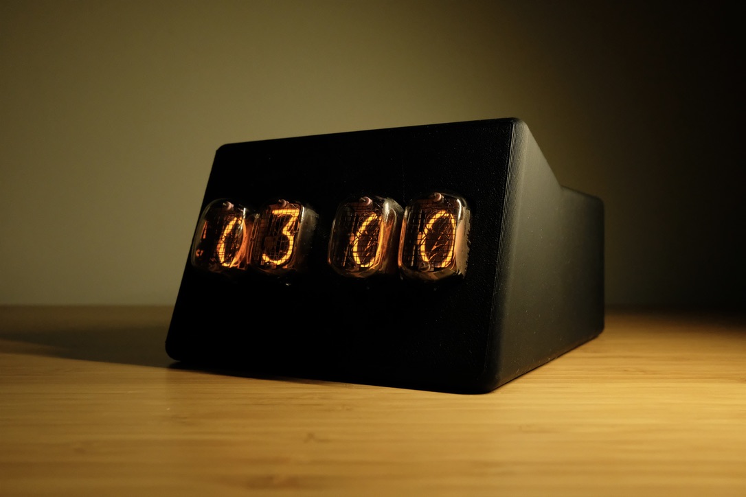
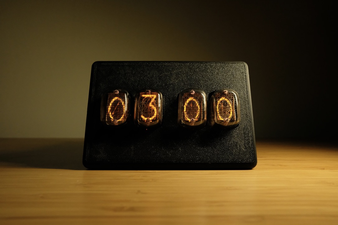
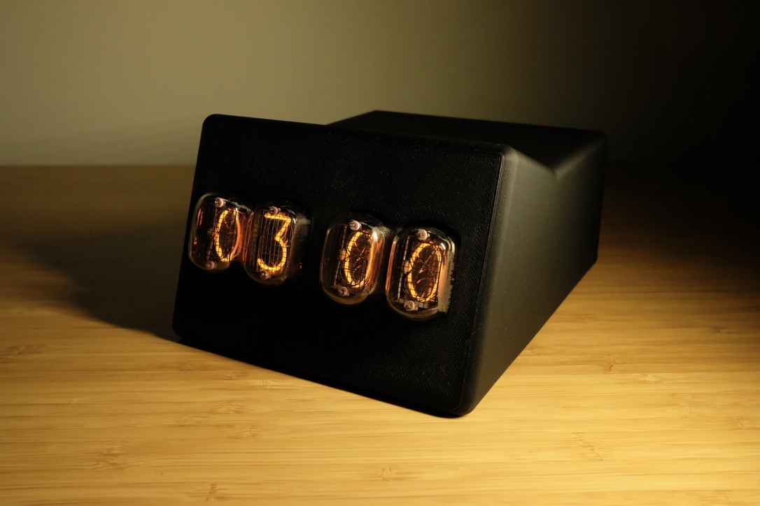
This is a nixie tube clock that tells basic time. Two push buttons are used to set the time, one for the hour and the other for the minute, and a mechanical switch turns the tubes on and off.
More info about Nixie Tubes.
Four IN-12A nixie tubes are used, which require ~170V DC to illuminate. The NCH8200HV is used to generate this voltage. The mechanical switch cuts power from this module, which allows the tubes to be turned off.
The nixie tubes are driven from four K155ID1 ICs, one IC per tube. These are very obsolete, but were made specifically to drive nixie tubes. The microcontroller used for this project is the STM32L010K4T6, an Arm Cortex-M0+ MCU. The RTC is used along with an external 32.768 kHz crystal to keep accurate time. Based on the one I've built, it consistently gains around two seconds per day.
The PCBs were designed using KiCad in two separate projects. These are found in the pcb directory.
There are two PCBs, the main board and the tube board. The main board is where all the main components live (MCU, ICs, capacitors, etc.). The tube board is specifically for the tube sockets to be soldered to, and then the tubes to plug into those. The main board and tube board plug into each other via header pins. The male header pins are soldered to one board, and the female to the other. This is how the current flows from the main board to the tube board. It also allows the PCBs to be disassembled if necessary.
The tubes should not be directly soldered to the PCB. Instead, solder tube sockets to the PCB, then plug the tubes into those. This will allow replacement of a tube if one breaks.
The 3d directory contains the files for 3D printing an enclosure for the completely assembled clock. These parts
require threaded brass inserts for the screws to secure everything. There are currently two versions of the
enclosure.
Original design.
Screws are M2.5 x 5 and M2.5 x 8.
The PCB Spacers are used for additional support between the boards to minimize stress on the header pins that connect
the tube board to the main board. Three of these spacers can be mounted while screwing the boards onto the front plate.
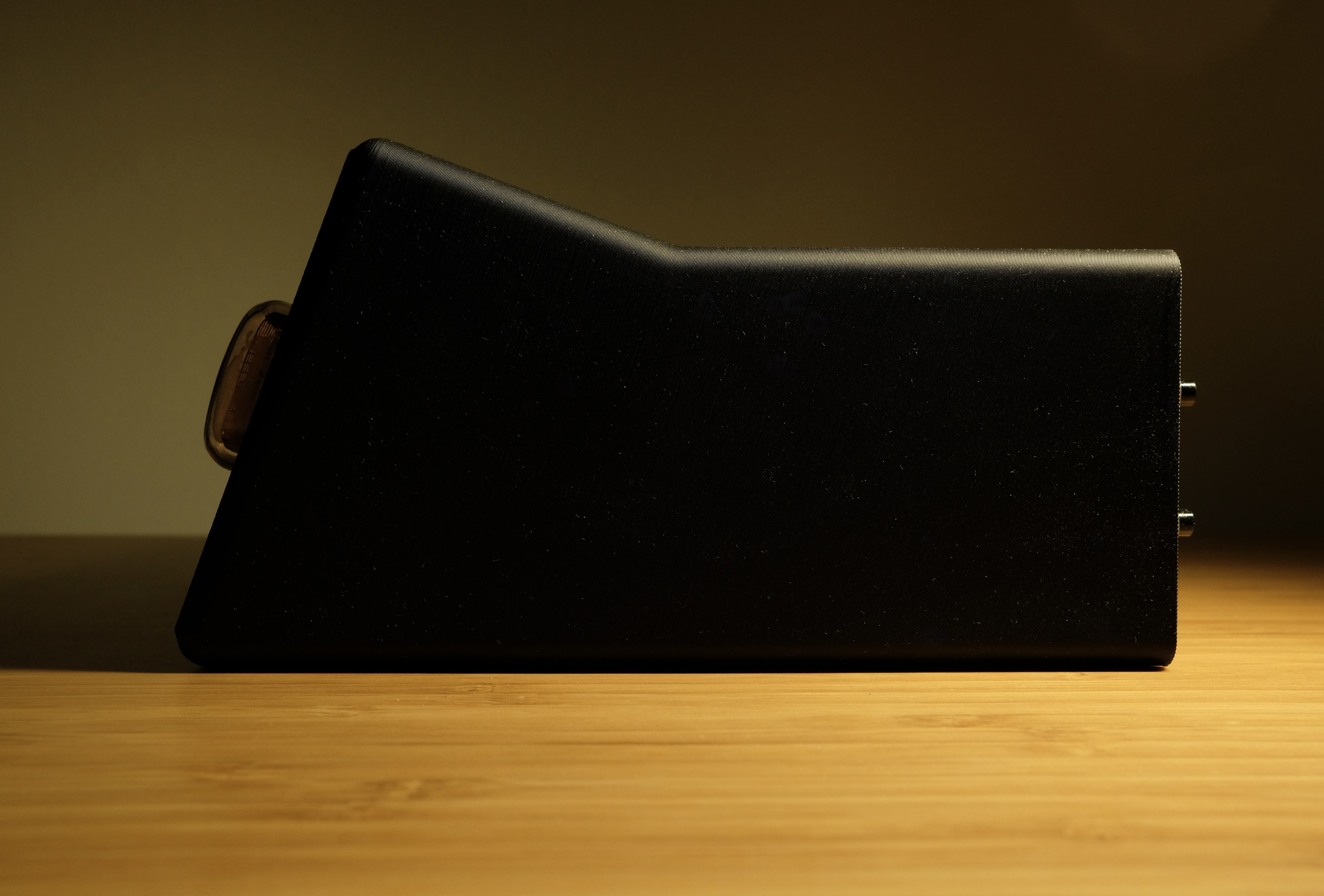
Inspired from Dieter Rams's design of the Braun DN40.
All screws are M2.5 x 5.
Four screws (top two alone are enough) can be used to secure the tube board to the PCB Mount. Easy to tap/screw
directly into the plastic.
The rest of the eight screws require the threaded brass inserts.
Due to the PCB using a Tag-Connect footprint for programming, the enclosure design pretty much requires the MCU to be programmed prior to assembling everything. If there is a desire to upload different firmware, then it will mostly have to be taken apart.
The DC jack that was used for this design requires to be mounted prior to soldering the wires to it. This restricts the enclosure from being completely removed without cutting the wires to this jack.
The firmware is a standard STM32 project set up using CLion and its integration with STM32CubeMX.
The only important thing to keep some form of is the cycle() function, which is found in Core/Src/nixie_display.c.
All this does is cycle through each number on every tube, which is supposed to prevent cathode poisoning. Unsure how
effective this is at the current frequency and duration.
In order to avoid additional hardware, a Tag-Connect footprint is used on the main board. This is used with an ST-LINK device (clones should work just fine) to program the MCU.
Update: It looks like this issue was fixed, I have not had time to test it out.
Unfortunately, using stlink doesn't seem to work with several STM32L0xxx MCUs. To get around this, the project can be opened up in STM32CubeIDE and flashed using the built in debugging functionality. Not ideal, but it works.
| Qty | Value | Footprint | References |
|---|---|---|---|
| 7 | 10k | Resistor_SMD:R_1206_3216Metric_Pad1.30x1.75mm_HandSolder | R7, R8, R9, R10, R11, R12, R13 |
| 4 | 100nF | Capacitor_SMD:C_1206_3216Metric_Pad1.33x1.80mm_HandSolder | C2, C3, C5, C15 |
| 4 | 1uF | Capacitor_SMD:C_1206_3216Metric_Pad1.33x1.80mm_HandSolder | C6, C7, C8, C14 |
| 4 | 74141DIP16 | nixiemisc:nixiemisc-DIP16 | M1, M2, M3, M4 |
| 4 | Conn_02x06_Odd_Even | Connector_PinHeader_2.54mm:PinHeader_2x06_P2.54mm_Vertical | J2, J3, J4, J5 |
| 2 | 12pF | Capacitor_SMD:C_1206_3216Metric_Pad1.33x1.80mm_HandSolder | C9, C10 |
| 1 | +9V | Connector_Wire:SolderWire-0.25sqmm_1x01_D0.65mm_OD1.7mm | H1 |
| 1 | 0.1uF | Capacitor_SMD:C_1206_3216Metric_Pad1.33x1.80mm_HandSolder | C1 |
| 1 | 0.22uF | Capacitor_SMD:C_1206_3216Metric_Pad1.33x1.80mm_HandSolder | C11 |
| 1 | 10uF | Capacitor_SMD:C_1206_3216Metric_Pad1.33x1.80mm_HandSolder | C4 |
| 1 | 200k | Resistor_SMD:R_1206_3216Metric_Pad1.30x1.75mm_HandSolder | R6 |
| 1 | 22pF | Capacitor_SMD:C_1206_3216Metric_Pad1.33x1.80mm_HandSolder | C12 |
| 1 | 22uF | Capacitor_SMD:C_1206_3216Metric_Pad1.33x1.80mm_HandSolder | C13 |
| 1 | 32.768kHz | Crystal:Crystal_SMD_SeikoEpson_MC306-4Pin_8.0x3.2mm_HandSoldering | Y1 |
| 1 | 33uH | Inductor_THT:RFS1113-333ME | L1 |
| 1 | 604k | Resistor_SMD:R_1206_3216Metric_Pad1.30x1.75mm_HandSolder | R5 |
| 1 | Conn_ARM_SWD_6 | Connector:Tag-Connect_TC2030-IDC-FP_2x03_P1.27mm_Vertical | J1 |
| 1 | FQU11P06TU | Package_TO_SOT_THT:TO-251-3-1EP_Horizontal_TabDown | Q1 |
| 1 | FerriteBead_Small | Capacitor_SMD:C_1206_3216Metric_Pad1.33x1.80mm_HandSolder | FB1 |
| 1 | GND | Connector_Wire:SolderWire-0.25sqmm_1x01_D0.65mm_OD1.7mm | H2 |
| 1 | HOURS + | Connector_Wire:SolderWire-0.25sqmm_1x01_D0.65mm_OD1.7mm | H5 |
| 1 | HOURS+GND | Connector_Wire:SolderWire-0.25sqmm_1x01_D0.65mm_OD1.7mm | H25 |
| 1 | LT3470ITS8PBF | Package_TO_SOT_SMD:SOT-23-8_Handsoldering | U4 |
| 1 | MAX6817 | Package_TO_SOT_SMD:SOT-23-6_Handsoldering | U2 |
| 1 | MINUTES + | Connector_Wire:SolderWire-0.25sqmm_1x01_D0.65mm_OD1.7mm | H6 |
| 1 | MINUTES+GND | Connector_Wire:SolderWire-0.25sqmm_1x01_D0.65mm_OD1.7mm | H24 |
| 1 | NCH8200HV | Module:NCH8200HV | U5 |
| 1 | STM32L010K4T6 | Package_QFP:LQFP-32_7x7mm_P0.8mm | U1 |
| 1 | SW_SPDT | Button_Switch_THT:SW_CuK_OS102011MA1QN1_SPDT_Angled | SW1 |
| 1 | Switch Input | Connector_Wire:SolderWire-0.25sqmm_1x01_D0.65mm_OD1.7mm | H3 |
| 1 | Switch Output | Connector_Wire:SolderWire-0.25sqmm_1x01_D0.65mm_OD1.7mm | H4 |
| 1 | TPS7A05SOT23 | Package_TO_SOT_SMD:TSOT-23_HandSoldering | U3 |
The 51 most common of 54 parts.


janikkaden/self-sufficient-audio-station
A solar-powered, self-sufficient audio station for outdoor exhibitions — ESP32 + DFPlayer, wakes from deep sleep on a button press and plays info tracks in three languages plus music.


gusmanb/logicanalyzer
24 channel, 100Msps logic analyzer hardware and software

polpo/picogus
Emulation of ISA sound cards and CD-ROM on Raspberry Pi Pico (GUS, SB/Adlib, MPU-401, Tandy, CMS, Panasonic CD-ROM) with USB mouse/joystick support


loxodes/vna
Under development open hardware microwave vector network analyzer
It measures 108 × 48.5 mm and has 4 copper layers, 1.6 mm thick.
54 parts, built around the STM32L010K4T6 and FQU11P06TU. The full list of its parts is on this page, with links to each part's symbol and footprint where PCBKit's library has them.
From the jamesSaporito/NixieClock repository on GitHub, at the commit this page was made from: the board is pcb/main_board/NixieSTM32.kicad_pcb and its schematic pcb/main_board/NixieSTM32.kicad_sch. PCBKit opens the board in the browser, with nothing to install.
Its repository publishes it under the MIT licence: you may reuse it on that licence's terms (keep the author's notice, and for a copyleft licence share your changes alike).