2 layers103 × 30.5 mm

 Jacube1234/GD-Hackpad
Hackpad for GD Platformers
Hackpad schematic is an open-source printed circuit board by Jacube1234, from the Jacube1234/GD-Hackpad repository on GitHub. It is a 2-layer board of 67 × 47 mm with 9 parts on 16 nets, routed with 88 tracks and 3 vias.
Its parts include 5 switches, 2 diodes and 1 IC.
View PCB on KiCanvas
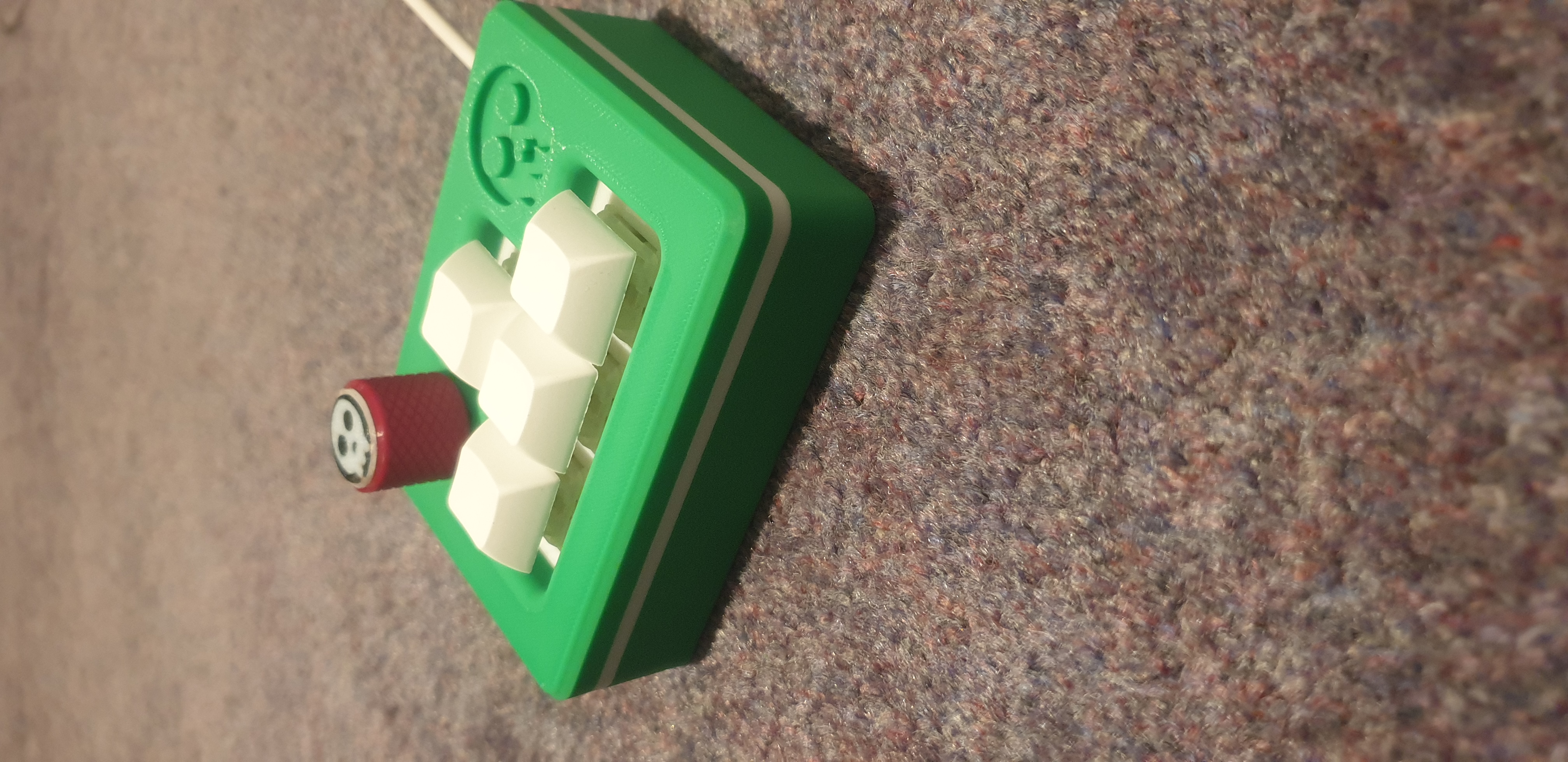
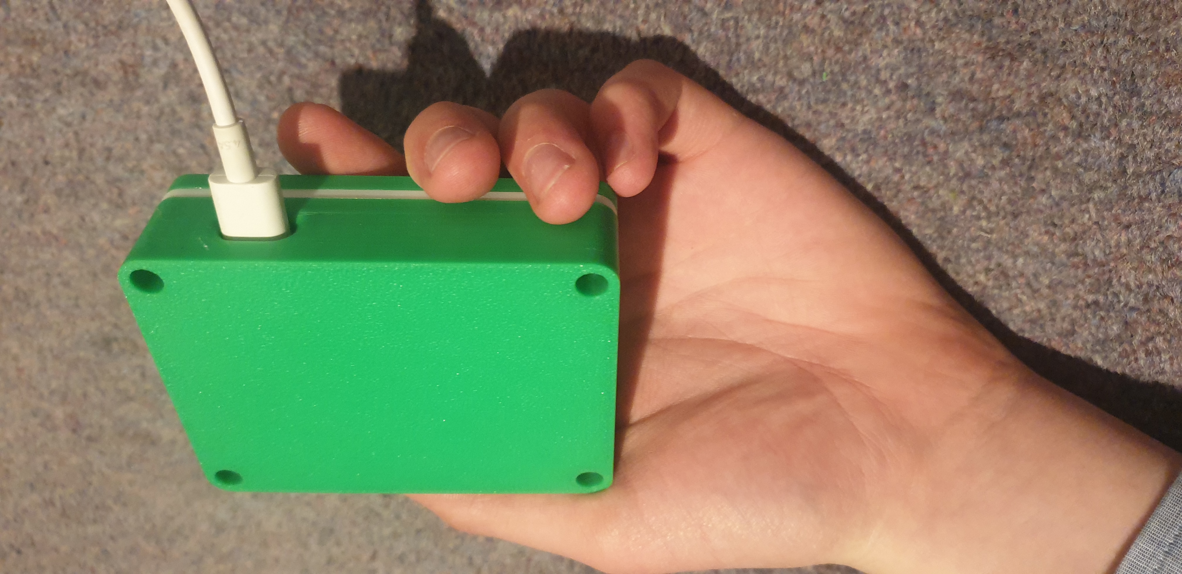
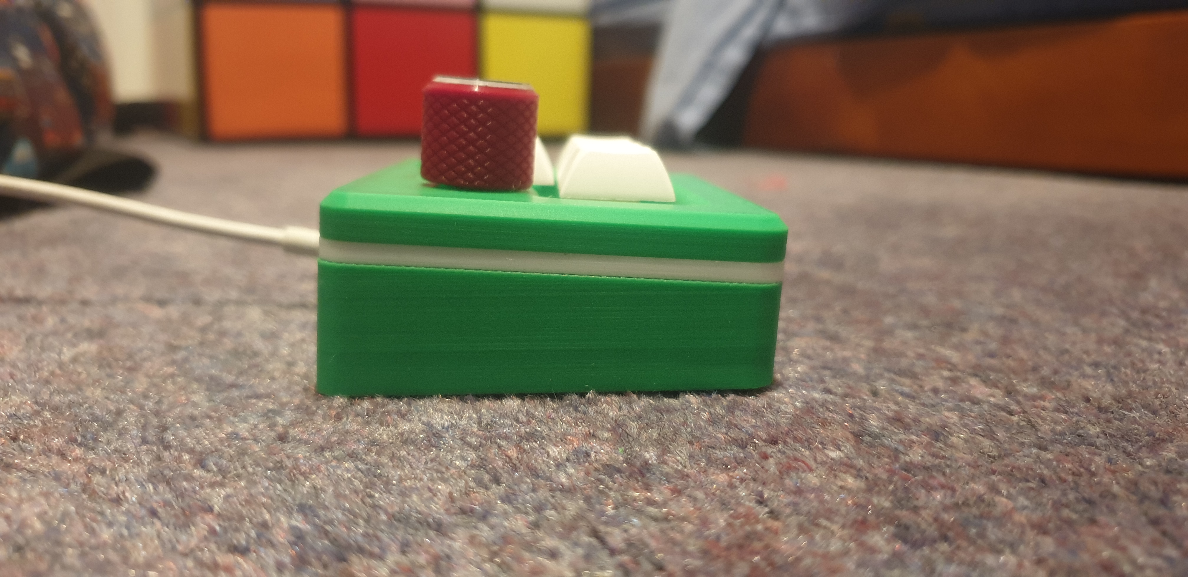
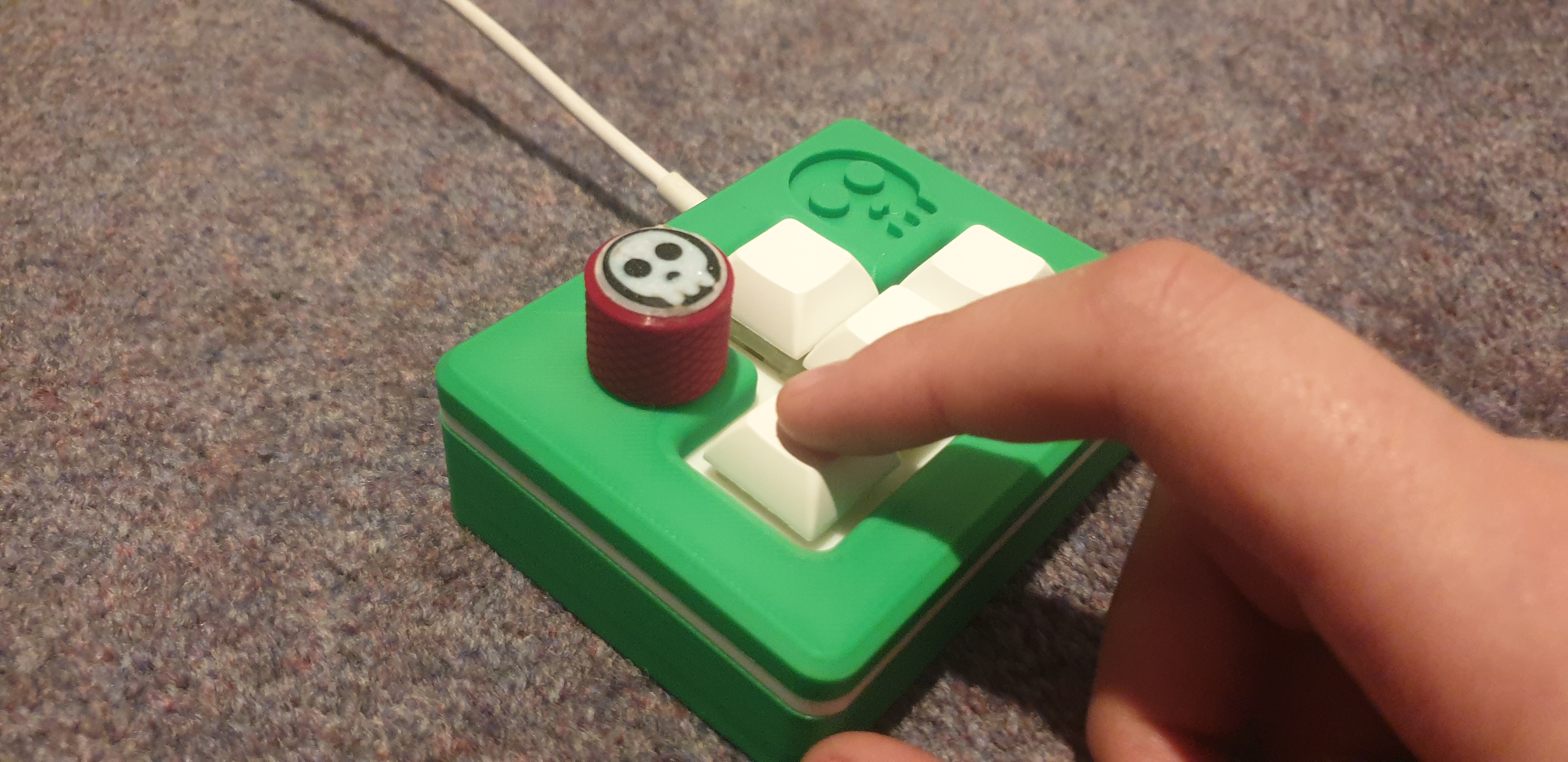
Note on images and files: The photos and physical build shown below do not have the RGB LEDs or don't have them working due to a footprint error on my design. However, the updated KiCad and Gerber files in this repository include the corrected LED routing, so if you fabricate a board using the current files, the LEDs will work fully as designed!
This is my Hackpad designed for the purpose to play Geometry Dash Platformer levels. Basically a DIY Sayo Device but cool yk. I chose this project as I am comfortable with Fusion 360, and a chance to learn a new program - Kicad.
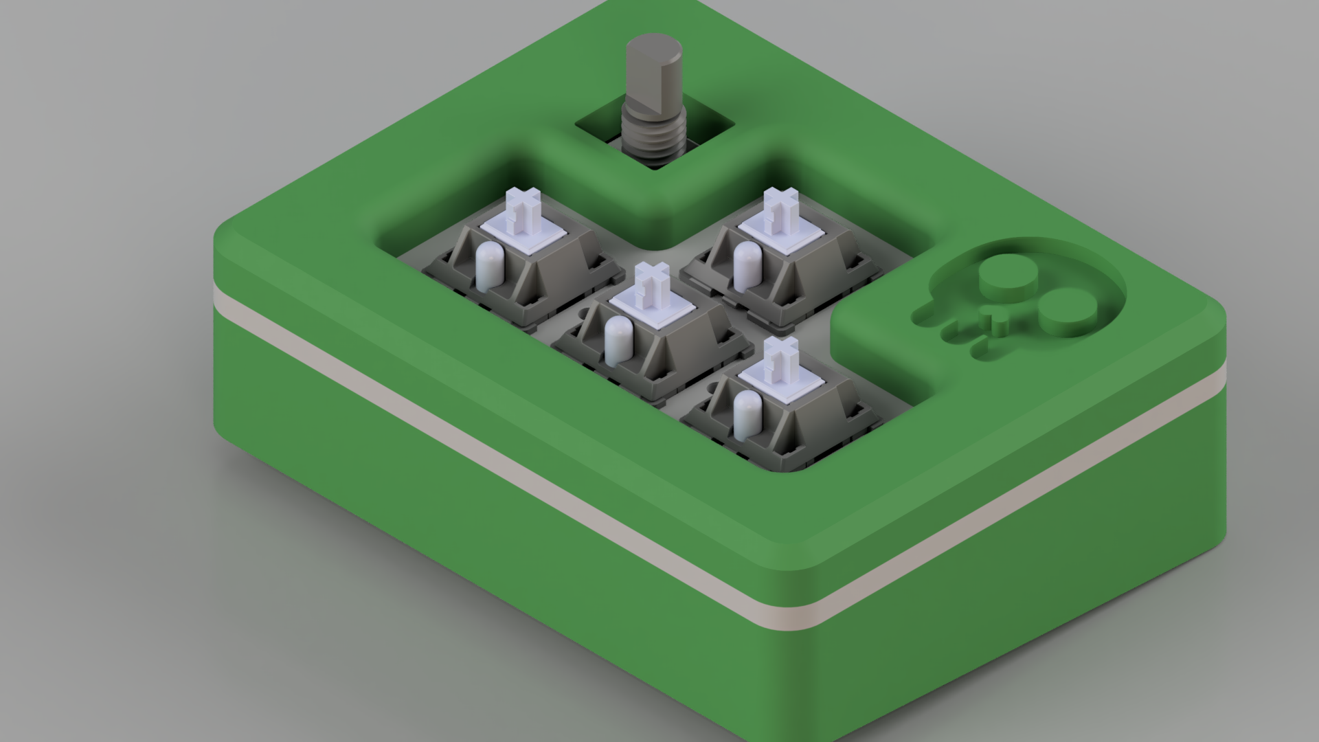
Everything fits together using 4 M3 Bolts and heatset inserts. 4 for the case.
It has 3 separate printed pieces. The base which has a tilt, the plate to hold the PCB, and the top shell.
Made in Fusion360.
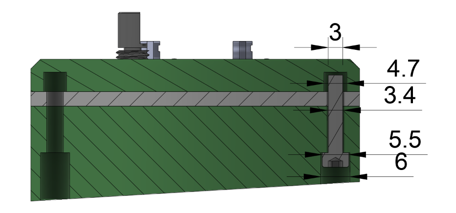
I added these elevated holes because the shell was 3mm tall, which is shorter than the depth needed for the heatset inserts. Still looks visually fine I reckon.
This also shows how it is assembled. The top plate and angled base sandwhich the plate the holds the switches.
Here's my PCB!💀 It was made in KiCad. I added the silkscreen image by using the build in image converter. I got a skull emoji off google, and placed it on my front silkscreen layer.
Schematic
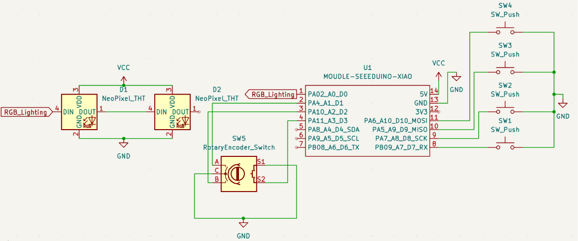
Layout
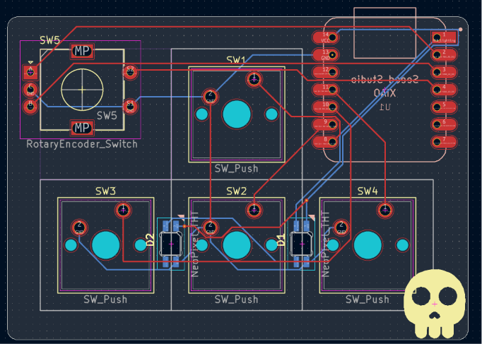
PCB
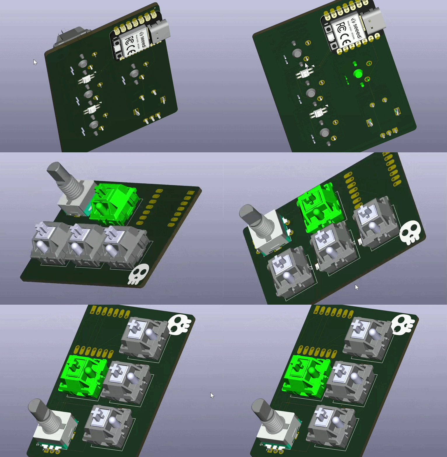
This hackpad uses KMK firmware for everything.
I might change the lights to change colour in the future.
There's 4 main folders: CAD, Firmware, PCB, and Production. The CAD folder contains the .step file for the case as a whole. It also contains the 3mf of the same thing, and the fusion f3z. The PCB folder contains .kicad_pcb, .kicad_pro, and .kicad_sch. The Firmware folder contains files for KMK firmware. The production folder has files for 3D printing and for the PCB printing.
Here should be everything you need to make this hackpad
.pcb .pro .sch filesNote that I will be getting most parts from Alex's Hackpad kit, and and the pcb ordered with the $15 grant.
README.md or hereInstall the heat-set inserts. Heat up your soldering iron and gently press the 4 M3 heat-set inserts into the 3D printed case. Take your time and let the heat do the work so you don't accidentally melt all the way through the plastic.
Put the software on the XIAO RP2040. Plug the microcontroller into your computer and drop the CircuitPython .uf2 file from here onto the RPI-RP2 drive. Basically follow this
Install KMK and your code. Put the kmk folder from the KMK firmware zip and the files from the Firmware folder in this repository onto the new CIRCUITPY drive.
Assemble the hardware. Snap your 4 MX switches through the 3D-printed plate so they sit securely. Sandwich your finished PCB between the base piece and the top shell, making sure the plate is aligned correctly.
Screw it together. Thread your 4 M3x16mm screws through the bottom of the case and into the heat-set inserts you installed in step 3. Try not to overtighten them.
Finishing touches. Slap your 4 blank white DSA keycaps onto the switches and push the custom 3D-printed knob onto the rotary encoder.
Hopefully it should work flawlessly because I have 100% tested the code.
Some stuff already mentioned elsewhere in this README.md
Hi guys
Bye guys
| Qty | Value | Footprint | References |
|---|---|---|---|
| 4 | SW_Push | Button_Switch_Keyboard:SW_Cherry_MX_1.00u_PCB | SW1, SW2, SW3, SW4 |
| 2 | NeoPixel_THT | Care Package:SK6812MINI-E_fixed | D1, D2 |
| 1 | LOGO | LOGO | G*** |
| 1 | MOUDLE-SEEEDUINO-XIAO | Care Package:XIAO-Generic-Hybrid-14P-2.54-21X17.8MM | U1 |
| 1 | RotaryEncoder_Switch | Rotary_Encoder:RotaryEncoder_Alps_EC11E-Switch_Vertical_H20mm | SW5 |
It measures 67 × 47 mm and has 2 copper layers, 1.6 mm thick.
9 parts. The full list of its parts is on this page, with links to each part's symbol and footprint where PCBKit's library has them.
From the Jacube1234/GD-Hackpad repository on GitHub, at the commit this page was made from: the board is PCB/GD-Hackpad/Hackpad schematic.kicad_pcb and its schematic PCB/GD-Hackpad working LED/GD.kicad_sch. PCBKit opens the board in the browser, with nothing to install.
Its repository states no licence, so its author keeps all rights: ask Jacube1234 before reusing the design.


FrameworkComputer/ExpansionCards
Reference designs and documentation to create Expansion Cards for the Framework Laptop

VoronDesign/Voron-Hardware
Cool Hardware designed by the Voron Design group

hackclub/OnBoard
💡 Join 1,000 teenagers and make your first PCB with a $100 grant!


adamws/kicad-kbplacer
KiCad plugin for automatic keyboard's key placement and routing