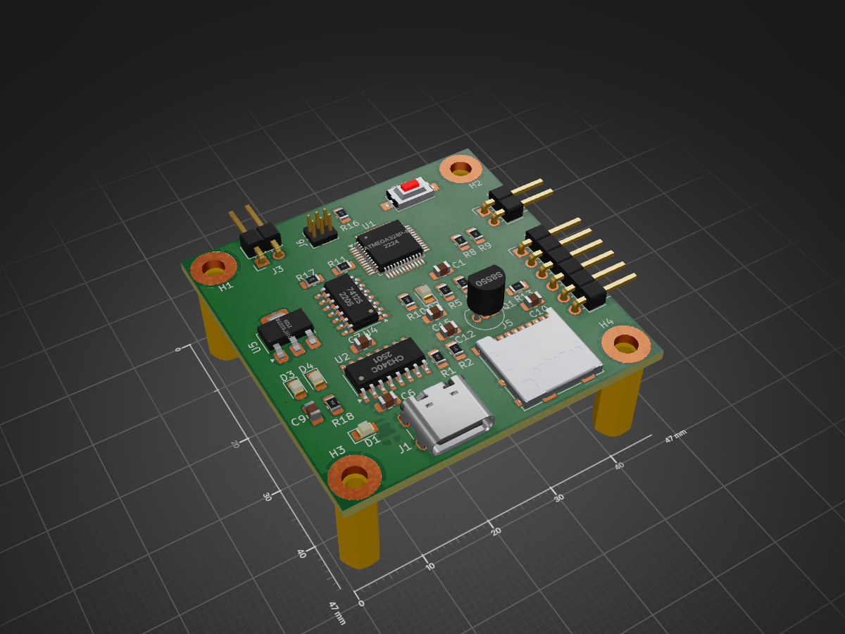
Loadcell PCB is an open-source printed circuit board by Jackiempty, from the Jackiempty/DAQ_PCB repository on GitHub. It is a 2-layer board of 47 × 47 mm with 57 parts on 76 nets, routed with 56 tracks and 1 via.
It is built around the ATMEGA328P-MU, CH340C and HX711, with the 4.7UF 16V and S8550 among its other parts. Its parts include 18 resistors, 15 capacitors, 6 ICs, 6 connectors and 4 diodes. It belongs with the sensors and measurement boards and the AVR (ATmega, ATtiny) boards of this library.
It measures 47 × 47 mm and has 2 copper layers, 1.6 mm thick.
What parts does the Loadcell PCB use?
57 parts, built around the ATMEGA328P-MU, CH340C, HX711 and 4.7UF 16V. The full list of its parts is on this page, with links to each part's symbol and footprint where PCBKit's library has them.
Where can I download the Loadcell PCB KiCad files?
From the Jackiempty/DAQ_PCB repository on GitHub, at the commit this page was made from: the board is Loadcell_PCB.kicad_pcb and its schematic Loadcell_PCB.kicad_sch. PCBKit opens the board in the browser, with nothing to install.
Can I use the Loadcell PCB design in my own project?
Its repository states no licence, so its author keeps all rights: ask Jackiempty before reusing the design.
Arduino-compatible development board PCB designed in KiCad. Features ATmega328P-M MCU, Micro USB interface, LM1117DT-5V onboard regulator, SMD resonator, dual 15-pin expansion headers, power LED, and reset switch.


 你的 dt 長達 0.1 秒,並且還要每隔 5 次才紀錄。發動機稍一次不過 1~2 秒,這樣採樣點才 4 個,基本無法分析。採樣率至少要到 80Hz。
 其實沒必要進入睡眠模式,我們沒有缺電,徒增資源浪費而已。
 不需要把時間單位轉成秒,從頭到尾用毫秒就好,因為我們需要高響應的結果。
 不應該刪掉負數,雖然水平推測出現負數的機率很低。但這也代表如果出現負數,我們可以用來 debug。並且如果有諸如垂直推測的情況(雖然也是幾乎不太可能做),負數就很重要了。


