Skip to the content
PCBKitNew board
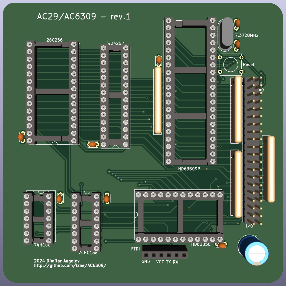
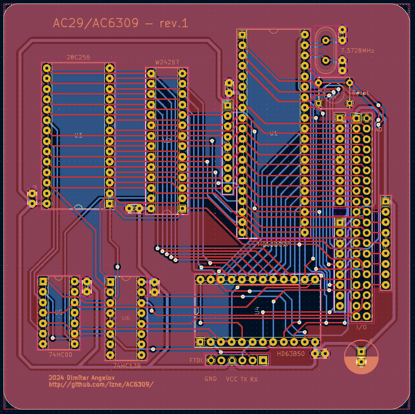
2 layers99.1 × 99.1 mmAC6309 Main, the printed circuit board in 3D

AC6309 Main

izne/AC63092

A minimalistic industrial computer running 6809/6309

Size
99.1 × 99.1 mm
Copper layers
2
Thickness
1.6 mm
Parts
23
Nets
64
Pads
256
Tracks, vias
615, 46
Pours
2
Routed
Yes
KiCad
KiCad 7 (file 20221018)
Created
5 Mar 2023
Updated
7 Jun 2025

Overview

AC6309 Main is an open-source printed circuit board by izne, from the izne/AC6309 repository on GitHub. It is a 2-layer board of 99.1 × 99.1 mm with 23 parts on 64 nets, routed with 615 tracks and 46 vias.

It is built around the 74HC00D and 74HC138. Its parts include 9 capacitors, 6 ICs, 2 connectors, 1 switch and 1 crystal. It belongs with the computers and single-board computers and retro computing and games boards of this library.

Main components

2

README

README.md

AC6309 Platform

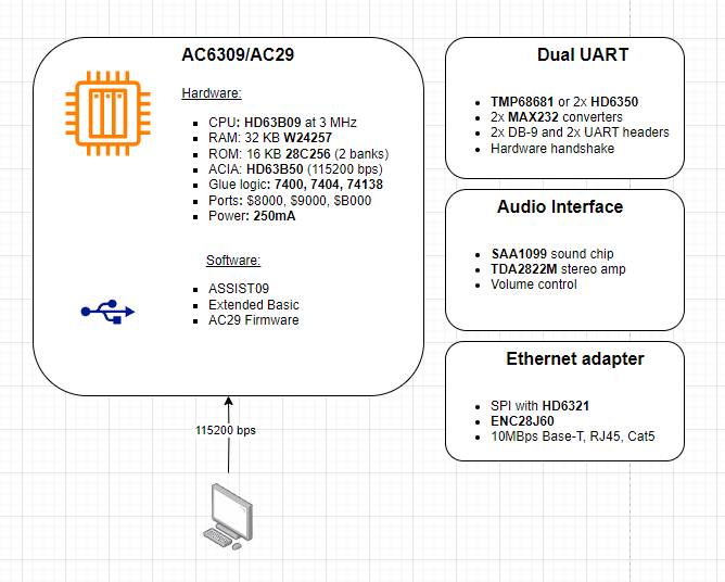
A minimalistic industrial computer core, based on Motorola 6809 architecture.

Purpose

Proof of concept custom 8-bit industrial computer with minimal device count implementation. Modular, low-power design, allowing easy expansion and customization per use case.

Dedication

AC29 is dedicated to my beloved father.
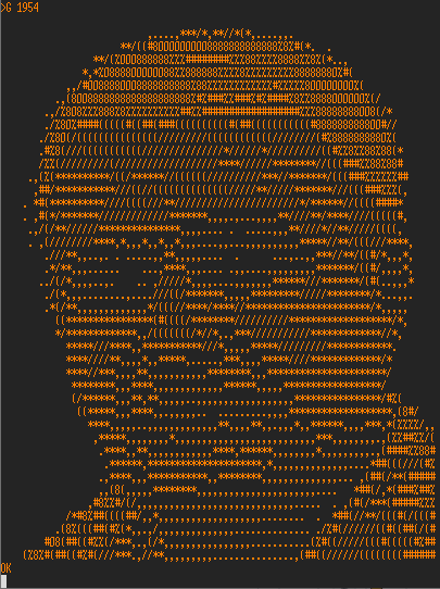
BAUS

AC29 projected configuration

AC29 Config

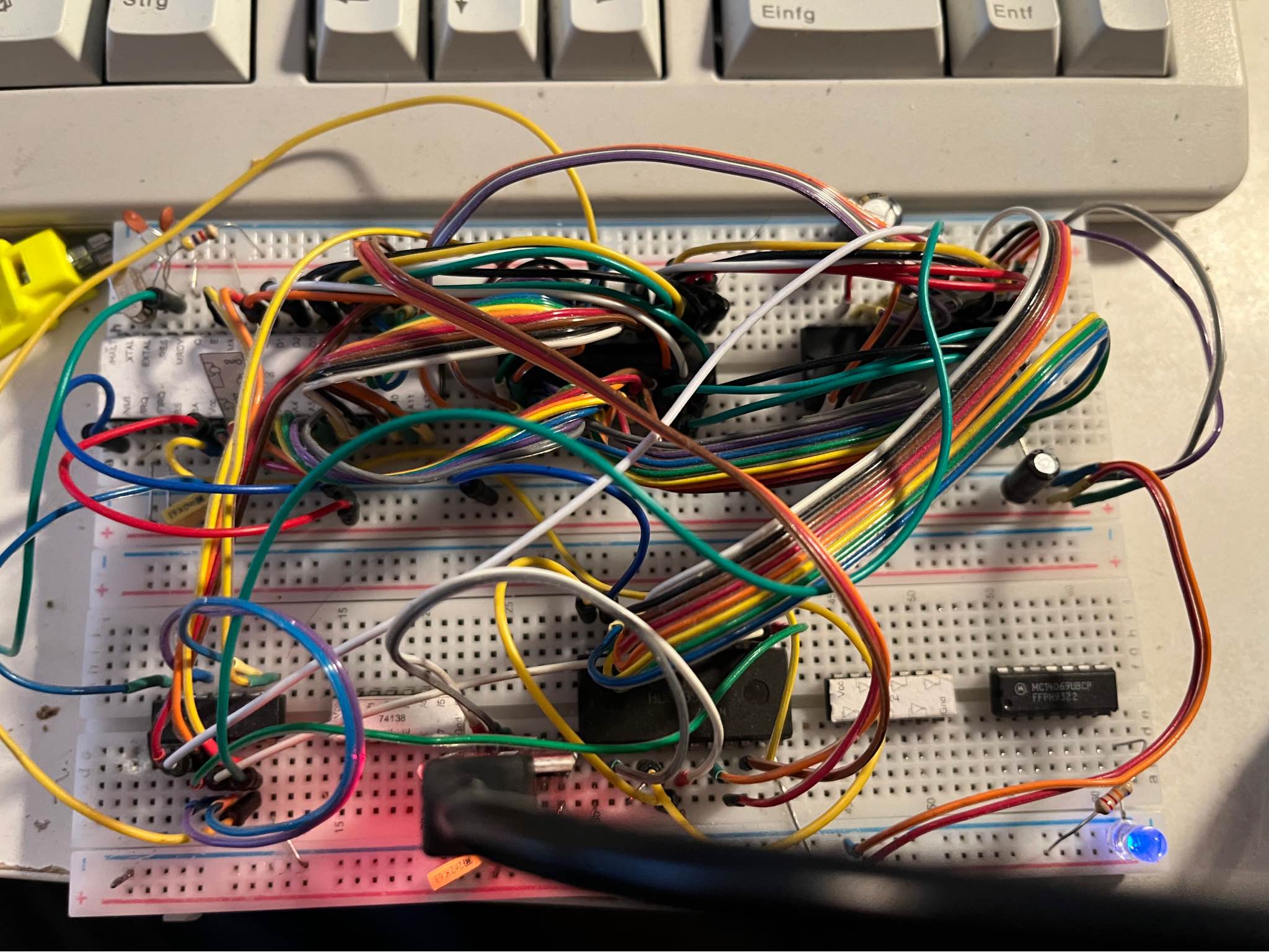
Prototype build

  • CPU: HD63B09 @ 1.8432MHz
  • RAM: 32KB W24257A
  • ROM: 8KB 28C256 (2x ROMs)
  • UART: HD63B50 (1MBps) on FT23 USB Serial
  • Address decoding: 74HCT00 & 74HCT138
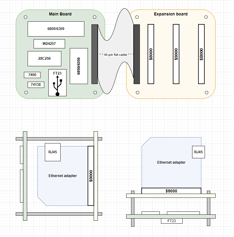
  • Expansion: 1x 40-pin header for expansion board with 3 slots mapped at $8000, $9000 and $B000
  • Power over USB

AC29 Breadboard

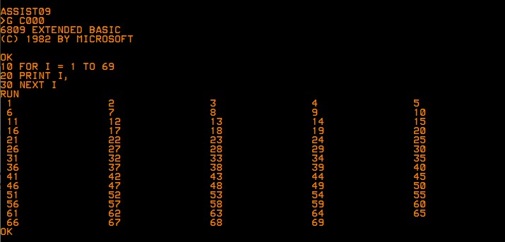
AC29 BASIC

Example physical layout

AC29 Layout

PCB Updates

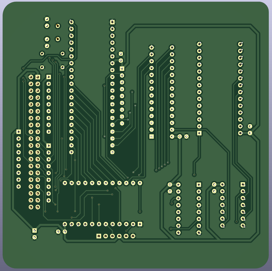
Current state of PCB design: AC29 PCB AC29 TOP AC29 BTM
System memory map

Address rangeDeviceSize
$0000-$7FFFRAM32KB
$8000-$8FFFExtension port #14KB
$9000-$9FFFExtension port #24KB
$A000-$AFFFUART4KB
$B000-$BFFFExtension port #34KB
$C000-$FFFFROM16KB

The 32KB of RAM is allocated from the bottom of the address range $0000 to $7FFF. The ROM is allocated at top 8KB of the address space starting $C000 to $DFFF.

The I/O mapping is allowing compatibility with existing BIOS images having ACIA on address 0xA000.

Writing the ROM image

Using the combination ROM image in Intel HEX format it needs first be turned into a binary image to be written to the EEPROM.

objcopy -I ihex -O binary combined.hex combined.bin

Write the resulting .bin file using the specially created EEPROM programmer for AT28C-series EEPROMs. Or any other.

promdude.exe -f combined.bin

As a note, burning the combined.bin (16K) onto 32K 28C256 has to be at the correct half. Optionally, a copy of combined.bin twice into the chip will do as well.

ROM switching

As the firmware is 16K and 28C256 (32K) chips are nowadays more accesible, two firmware images could be stored in the full 32K capacity of the chip. A ROM switching key to be implemented on the board, to switch the higher or lower part of the chip to be "visible" (A14) at boot.

Communication

The system communicates with a terminal via USB serial connection using the included ACIA device and its UART capability, coupled with an FTDI232 header. Terminal serial port settings: 115200 baud, 8n1, no hardware handshake yet.

Software checklist

  • Run ASSIST09 and Extended BASIC
  • Write basic program (asm)
  • Cross-compile on host machine
  • Easy program transer via ASSIST09 Load (S19)
  • Use of high level C code (CMOC)

Hardware checklist

  • Breadboard prototype running
  • Revision 1 completion and PCB fabrication
  • Extended addressing ("A" - four internal devices, "B" - four external devices)
  • Expansion board with easy coupling
  • 28C16-based address decoder
  • Expansion card: Am9511 card (Am9511, 3MHz osc, 5to12Vbuck)
  • Expansion card: Tape interface
  • Expansion card: TMP68681 / 2x RS232 / 115200 bps (own osc)
  • Expansion card: Ethernet adapter (ENC28J60)
  • Expansion card: SAA1099 + TDA2822 audio interface
  • Expansion card: VGA and PS/2 (Arduino)
  • Expansion card: VGA and PS/2 (MC6845/HD6321)
  • Expansion card: VGA (EF9367)
  • Expansion card: Keyboard controller (XT, AT, PS/2, USB)

Toolchain

Emulators


Prerequisites

The schematics and PCB design is made with KiCad

References and inspiration:

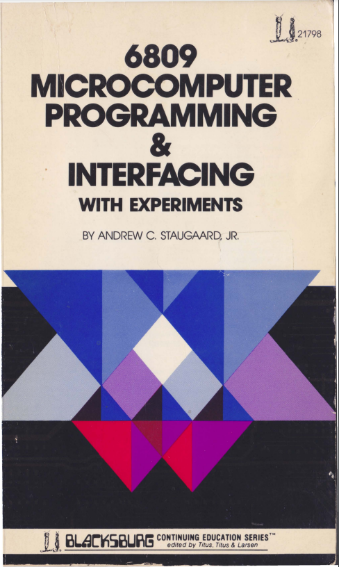
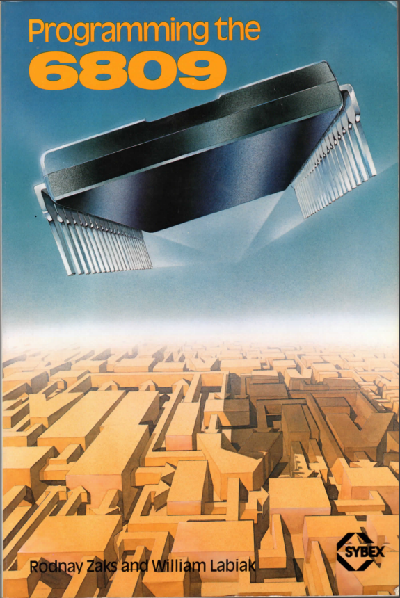
Some great oldschool books:

https://colorcomputerarchive.com/repo/Documents/Books/Programming%20the%206809%20(Rodney%20Zaks%20and%20William%20Labiak).pdf

https://www.chibiakumas.com/6809/

Parts

23
QtyValueFootprintReferences
6100 nFCapacitor_THT:C_Disc_D3.0mm_W2.0mm_P2.50mmC4, C5, C6, C7, C8, C9
4R_Network08Resistor_THT:R_Array_SIP9RN1, RN2, RN3, RN4
215pFCapacitor_THT:C_Disc_D3.0mm_W1.6mm_P2.50mmC2, C3
1100 uFCapacitor_THT:CP_Radial_D8.0mm_P2.50mmC1
128C256Package_DIP:DIP-28_W15.24mm_SocketU3
17.3728 MHzCrystal:Crystal_HC49-4H_VerticalY1
174HC00Package_DIP:DIP-14_W7.62mm_SocketU5
174HC138Package_DIP:DIP-16_W7.62mm_SocketU6
1FTDIConnector_PinSocket_2.54mm:PinSocket_1x06_P2.54mm_VerticalJ2
1HD63B09PPackage_DIP:DIP-40_W15.24mm_SocketU1
1HD63B50Package_DIP:DIP-24_W15.24mm_SocketU4
1I/OConnector_PinHeader_2.54mm:PinHeader_2x20_P2.54mm_VerticalJ1
1ResetButton_Switch_THT:SW_Tactile_Straight_KSL0Axx1LFTRSW1
1W24257Package_DIP:DIP-28_W7.62mm_SocketU2

Questions

How big is the AC6309 Main PCB?

It measures 99.1 × 99.1 mm and has 2 copper layers, 1.6 mm thick.

What parts does the AC6309 Main use?

23 parts, built around the 74HC00D and 74HC138. The full list of its parts is on this page, with links to each part's symbol and footprint where PCBKit's library has them.

Where can I download the AC6309 Main KiCad files?

From the izne/AC6309 repository on GitHub, at the commit this page was made from: the board is AC6309_Main/AC6309_Main.kicad_pcb and its schematic AC6309_Main/AC6309_Main.kicad_sch. PCBKit opens the board in the browser, with nothing to install.

Can I use the AC6309 Main design in my own project?

Its repository states no licence, so its author keeps all rights: ask izne before reusing the design.

Similar boards

  • 2 layers99.1 × 99.1 mmAv board, the printed circuit board in 3D

    Av board

    rjw57/buri

    This repository contains my work on designing, building and programming a 6502 microcomputer from scratch. The 6502 was the CPU used in the original Apple 1, BBC Microcomputer, NES console and many other systems from…

    42 parts68MIT
  • 2 layers208 × 110 mm8 16 computer 2, the printed circuit board in 3D

    8 16 computer 2

    halfburnttoast/TCPU816-v1

    Version 1.1 of my 8-bit, TTL computer.

    120 parts21
  • 2 layers335 × 218.6 mmMSX Goauld, the printed circuit board in 3D

    MSX Goauld

    leomanes/stargate

    Stargate MSX Compatible Computer

    298 parts18GPL-3.0
  • 2 layers254 × 160 mmDeck65, the printed circuit board in 3D

    Deck65

    and3rson/deck65

    Simple SBC based on 65c02s

    183 parts16GPL-3.0
  • 2 layers178 × 711 mmMSAP-2 rev.A SMD, the printed circuit board in 3D

    MSAP-2 rev.A SMD

    mehrantsi/MSAP-2

    An 8-bit computer. Successor to MSAP-1

    658 parts13MIT
  • 2 layers335 × 250 mmACE Board, the printed circuit board in 3D

    ACE Board

    acwright/6502-ACE

    6502-ACE 8-Bit Retro Computer Project

    205 parts12CERN-OHL-P-2.0
  • 2 layers100 × 100 mmCaveboard, the printed circuit board in 3D

    Caveboard

    and3rson/caveboard

    https://youtu.be/Klj2Q3trmW8

    44 parts12MIT
  • 2 layers225.1 × 167.8 mm6502 computer, the printed circuit board in 3D

    6502 computer

    jp0409hlh/6502_computer

    A computer based on Ben Eater's 6502 series

    81 parts7