2 layers140.5 × 30 mm
Type e
google/mozc-devices
Circuit diagrams and firmware source code for Gboard DIY keyboards
16 parts3kApache-2.0

 ivanpost24/p2p-lora-robot2
A tele-operated mobile robot operating over the LoRa physical layer. For WIoT Sp ’26 final project.
Training Robot is an open-source printed circuit board by ivanpost24, from the ivanpost24/p2p-lora-robot repository on GitHub. It is a 2-layer board of 87.1 × 87 mm with 16 parts on 20 nets, routed with 190 tracks and 22 vias.
Its parts include 3 ICs, 3 connectors, 2 resistors, 1 diode and 1 switch. It belongs with the robots and motor control boards of this library.
Authored by: Farjan Ahmed, Carlos Giron, Ivan Post
This is our final project for CS 4501: Wireless for the Internet of Things. It is a prototype system for controlling a mobile robot over long distances (from our observation, up to 0.32 km) using the LoRa physical layer protocol on Heltec ESP32 v3 LORA boards. It is designed to operate on the 915 MHz unlicensed band in the United States, which means you do not need an amateur radio license to use it. This is a video of an operator controlling the robot from about 0.3 km away; the control latency is primarily due to delays in the video feed and is under 500 ms in practice. The exact feasible range will depend on environmental factors.
We have provided instructions below to reproduce our prototype.
Additional pcb relevant components such as resistors, switches, and connectors are shown in this schematic:
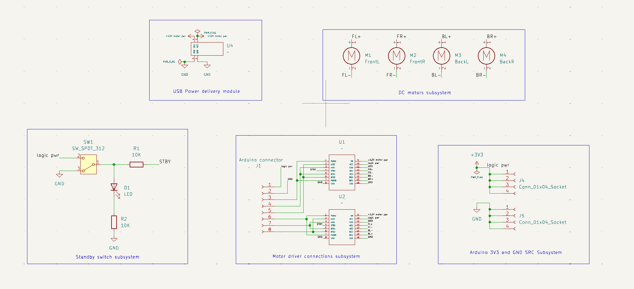
The KiCad files for editing the schematic and gerbers for ordering PCBs are included in the "/KiCad" directory.
Mount the breakout boards for motor drivers and modules onto their respective locations on the pcb:
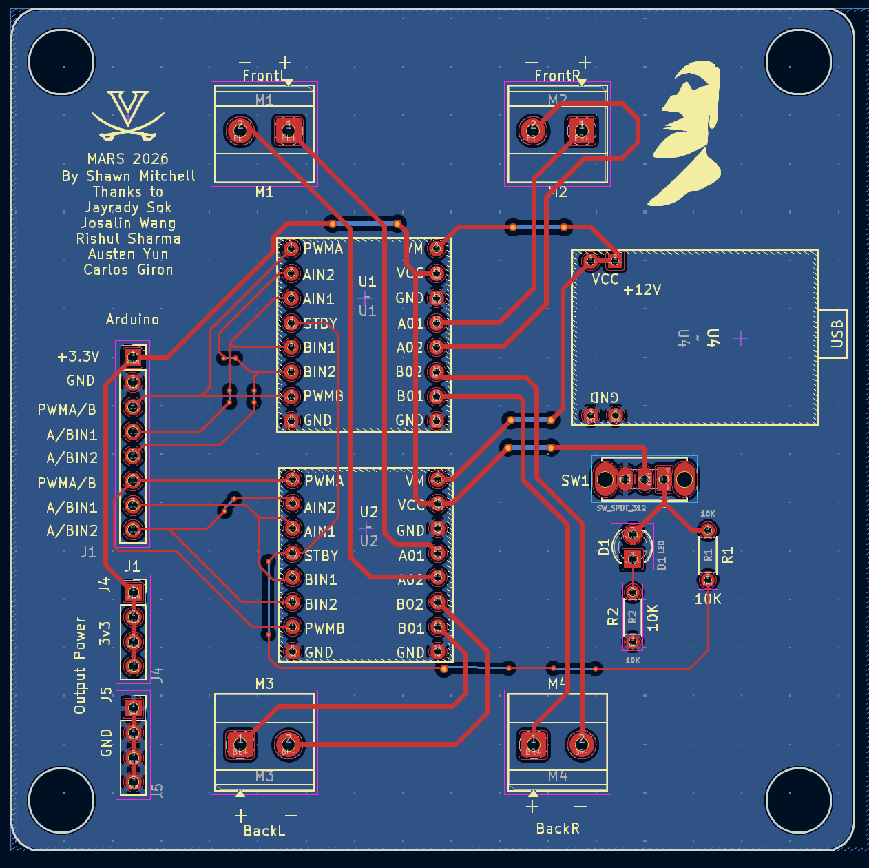
Assignments for the peripheral robot device are as follows:
These pins are used to set the direction of motors and speed of motors as they are connected to tb6612fng motor drivers. You MUST NOT power the motor drivers using the 3v3 pins of the Heltec board. Due to a hardware issue it seems that these boards are unable to power the motor drivers and remain on for operation. You must use a seperate 3v3 source to power the drivers.
In our case we used an Arduino Uno R3 to deliver 3v3, but a simple battery should suffice. It is important to remember to ground both Arduino and Heltec on the same rail otherwise reference issues for digital logic occur.
Assignments for the central controller are as follows:
Although the datasheet recommends using 5V as input, our code was designed around using 3v3.
This project uses PlatformIO, so configuring the project locally should be simple. Flash the Heltec v3 on the robot with the lora-peripheral code, and flash the Heltec v3 on the controller with the lora-central code. Everything should start automatically without any user input.
After code has been flashed onto the central and peripheral devices start the device as follows:
If the PD module and onboard led are on then the robot is ready for operation if the devices were flashed successfully and connections were correct.
| Qty | Value | Footprint | References |
|---|---|---|---|
| 2 | 10K | Resistor_THT:R_Axial_DIN0204_L3.6mm_D1.6mm_P5.08mm_Horizontal | R1, R2 |
| 2 | ~ | Library:TB_breakout_motor_driver | U1, U2 |
| 1 | 3v3 | Connector_PinSocket_2.54mm:PinSocket_1x04_P2.54mm_Vertical | J4 |
| 1 | Arduino connector | Connector_PinSocket_2.54mm:PinSocket_1x08_P2.54mm_Vertical | J1 |
| 1 | BackL | TerminalBlock_Phoenix:TerminalBlock_Phoenix_MKDS-1,5-2_1x02_P5.00mm_Horizontal | M3 |
| 1 | BackR | TerminalBlock_Phoenix:TerminalBlock_Phoenix_MKDS-1,5-2_1x02_P5.00mm_Horizontal | M4 |
| 1 | FrontL | TerminalBlock_Phoenix:TerminalBlock_Phoenix_MKDS-1,5-2_1x02_P5.00mm_Horizontal | M1 |
| 1 | FrontR | TerminalBlock_Phoenix:TerminalBlock_Phoenix_MKDS-1,5-2_1x02_P5.00mm_Horizontal | M2 |
| 1 | GND | Connector_PinSocket_2.54mm:PinSocket_1x04_P2.54mm_Vertical | J5 |
| 1 | LED | LED_THT:LED_D3.0mm | D1 |
| 1 | LOGO | Library:Moai4 | G*** |
| 1 | LOGO | Library:UVA_logo_new | G*** |
| 1 | SW_SPDT_312 | Button_Switch_THT:SW_Slide_SPDT_Straight_CK_OS102011MS2Q | SW1 |
| 1 | ~ | Library:PD Module | U4 |
google/mozc-devices
Circuit diagrams and firmware source code for Gboard DIY keyboards

conorpp/u2f-zero
U2F USB token optimized for physical security, affordability, and style

rusefi/rusefi
rusefi - GPL internal combustion engine control unit

VoronDesign/Voron-Hardware
Cool Hardware designed by the Voron Design group

hoglet67/RGBtoHDMI
Bare-metal Raspberry Pi project that provides pixel-perfect sampling of Retro Computer RGB/YUV video and conversion to HDMI

hackclub/OnBoard
💡 Join 1,000 teenagers and make your first PCB with a $100 grant!


It measures 87.1 × 87 mm and has 2 copper layers, 1.6 mm thick.
16 parts. The full list of its parts is on this page, with links to each part's symbol and footprint where PCBKit's library has them.
From the ivanpost24/p2p-lora-robot repository on GitHub, at the commit this page was made from: the board is kicad/Training_Robot.kicad_pcb and its schematic kicad/Training_Robot.kicad_sch. PCBKit opens the board in the browser, with nothing to install.
Its repository states no licence, so its author keeps all rights: ask ivanpost24 before reusing the design.