

2 layers37 × 19 mm
Passive rpi hub75-adapter
hzeller/rpi-rgb-led-matrix
Controlling up to three chains of 64x64, 32x32, 16x32 or similar RGB LED displays using Raspberry Pi GPIO
2 parts4.4kGPL-2.0

 islandcontroller/jtag-wire-adapter9
A compact adapter for connecting J-Link debug probes to generic JTAG/SWD targets
Jtag wire adapter is an open-source printed circuit board by islandcontroller, from the islandcontroller/jtag-wire-adapter repository on GitHub, published under the CERN-OHL-P-2.0 licence. It is a 2-layer board of 21.6 × 27.9 mm with 2 parts on 19 nets, routed with 27 tracks and 17 vias.
It belongs with the interfaces and adapters and sensors and measurement boards of this library.


A compact adapter board for connecting SEGGER J-Link debug probes to generic JTAG/SWD targets using a set of flying wires.
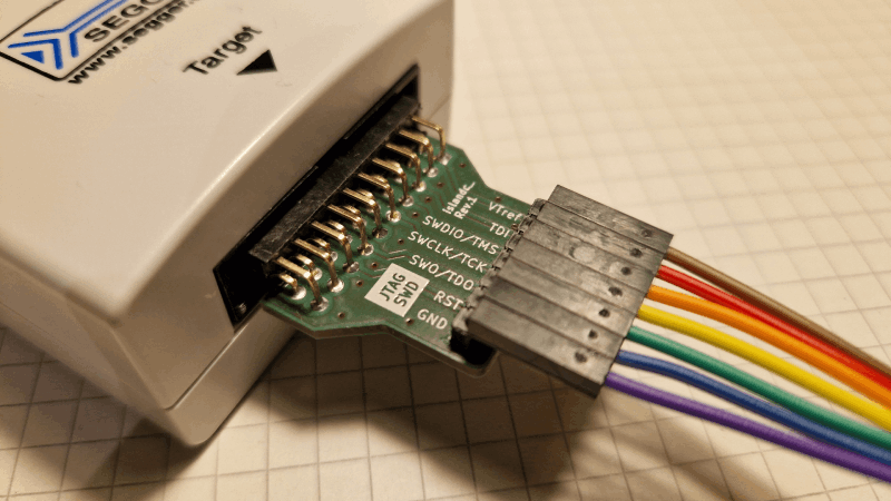
View Schematic 📄 or PCB Preview 🌐.
Interested? Click the button below to push this project to AISLER and get your PCB fabricated.
This adapter can be used to interface a SEGGER J-Link debug probe to a generic JTAG or SWD target, using .1" DuPont-style jumper wires. This low cost solution can be especially useful for academic users of J-Link EDU probes, as it doesn't require special connector hardware to be fitted on target project boards.
The parts are generic and can be found pretty much anywhere on the internet.
| Designator | Description |
|---|---|
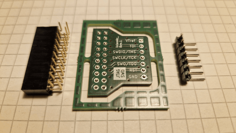
J1 | Right-angle socket header, 2x10 contacts, .100" spacing Suggested: SFH11-PBPC-D10-RA (Digikey S9205-ND) |
J2 | Right-angle pin header, 1x7 contacts, .100" spacing |
Prototype PCBs were fabricated in the EU at AISLER B.V. using their integrated KiCad plugin. See photos for further details.
The selected stacked-row header seems to be just short enough to accidentally fit with a column offset. A wider connector should be selected to prevent wrong connection.
SFH11-PBPC-D10-RA (available from Digikey as S9205-ND).A tool compatibility test was performed using a SEGGER J-LinkEDU emulator and a "blue pill"-type STM32 board.


If not stated otherwise within the specific file, the contents of this project are licensed under the CERN Open Hardware Licence Version 2 - Permissive. The full license text is provided in the LICENSE document.
SPDX-License-Identifier: CERN-OHL-P-2.0This licensing model is compliant with the Open Source Hardware Definition 1.0.
| Qty | Value | Footprint | References |
|---|---|---|---|
| 1 | Conn_01x07_Pin | Connector_PinHeader_2.54mm:PinHeader_1x07_P2.54mm_Horizontal | J2 |
| 1 | Conn_02x10_Odd_Even | Connector_PinSocket_2.54mm:PinSocket_2x10_P2.54mm_Horizontal | J1 |
It measures 21.6 × 27.9 mm and has 2 copper layers, 1.6 mm thick.
2 parts. The full list of its parts is on this page, with links to each part's symbol and footprint where PCBKit's library has them.
From the islandcontroller/jtag-wire-adapter repository on GitHub, at the commit this page was made from: the board is pcb/jtag-wire-adapter.kicad_pcb and its schematic pcb/jtag-wire-adapter.kicad_sch. PCBKit opens the board in the browser, with nothing to install.
Its repository publishes it under the CERN-OHL-P-2.0 licence: you may reuse it on that licence's terms (keep the author's notice, and for a copyleft licence share your changes alike).
hzeller/rpi-rgb-led-matrix
Controlling up to three chains of 64x64, 32x32, 16x32 or similar RGB LED displays using Raspberry Pi GPIO


adamws/kicad-kbplacer
KiCad plugin for automatic keyboard's key placement and routing

Luos-io/luos_engine
Open-source and real-time orchestrator for cyber-physical-systems, to easily design, test and deploy embedded applications and digital twins.

NVNTLabs/switch2-SDEX2M2
Micro SD Express to M.2 NVME Adapter for Nintendo Switch 2

BlueSCSI/BlueSCSI-v2
BlueSCSI v2/Ultra - an open source, open hardware, SCSI emulator using the Pi Pico PR2040 and Pico 2 RP2350

ohmtech-rdi/eurorack-blocks
Software to Hardware Prototyping for Eurorack using C++, Max/Gen~ or Faust
