

2 layers
Encoder
byrantech/laptop
anyon_e, a highly integrated, high end, open source laptop. Attempt the impossible.
7 parts4.3kMIT

better then flipper zero.
Tuffboy is an open-source printed circuit board by ishantdahiya1501-ctrl, from the ishantdahiya1501-ctrl/tuffboy repository on GitHub. It is a 2-layer board of 52.5 × 90.5 mm with 7 parts on 43 nets, routed with 176 tracks and 28 vias.
Its parts include 6 ICs and 1 connector. It belongs with the ESP32 and RISC-V boards of this library.
NOTE for admin : I have been working on this project form then 70+ hrs i have made so much progress and learned so many things you asked me add the things like bom and how will the make this those things are now added also your review stats that "Some of your journals although they have what you've done, kind of doesn't justify why you got the hours and has a brief explanation" I understand that you need proper journals and all i have tried to make the journals bigger and they describe what i did but thee main problem i myself does not remember what i did like 2 or 3 weeks ago that's why i can't full full fill your journal criteria also you guys states that the hours does not justify tbh i am very very new in this tech field i learned kicad from ground zero that's why it takes time to make the pcb to find the parts for the pcb design i am not a pro at the end so if you check any lapse with the devlog you can see that was working only not afk but my speed has now increased also some of the journals were i shifted to linux the lapse are not there becuase i thought that lookout only works in windows so pls keep that in mind. I really hope that this time my project gets selected.
A handheld multi-tool inspired by the Flipper Zero, but built around the ESP32-C5 Devkit C with Dual Band (2.4GHz + 5Ghz), and a big idea: an expansion port that lets you bolt on a whole second microcontroller (Black Pill, or basically any 3.3V dev board).
This is the part that makes TuffBoy ~200× more flexible than a Flipper — instead of being stuck with only 2.4 GHz WiFi we have a breakthrough with the support of 5GHz, opening the door to WiFi security testing, along with support for plugging in whatever co-processor the task needs.


TuffBoy so far:
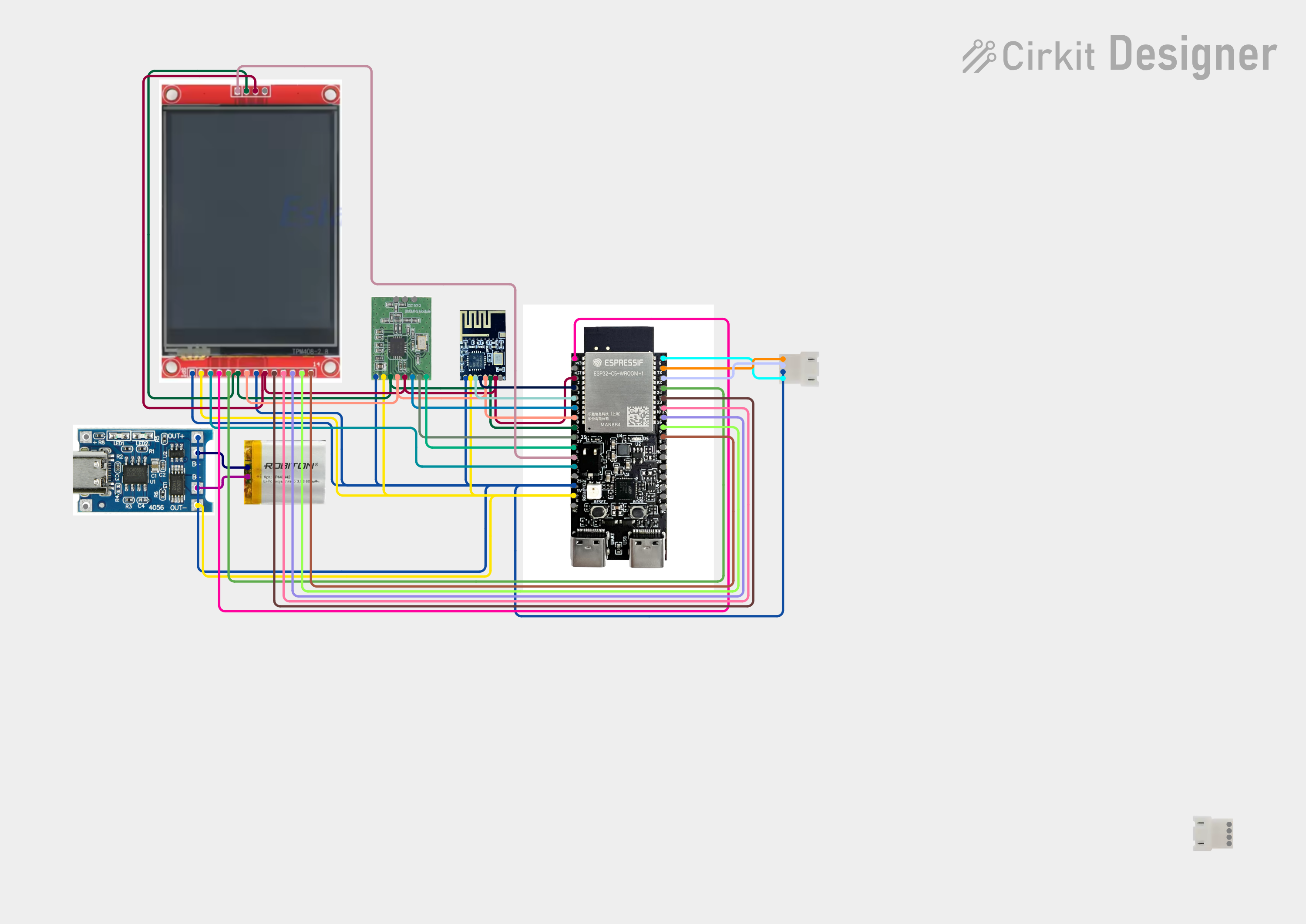
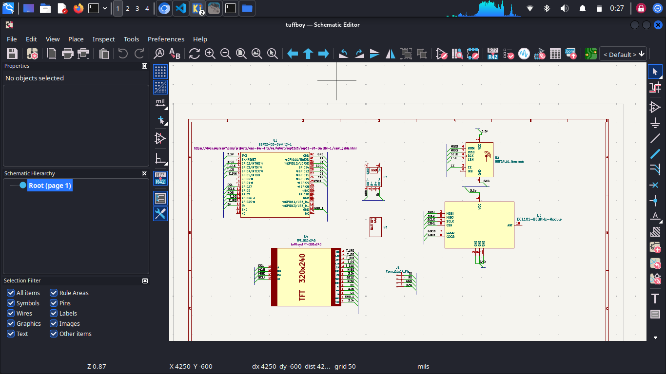
Circuit diagram:
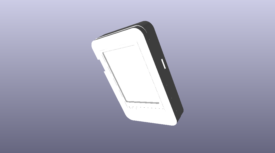
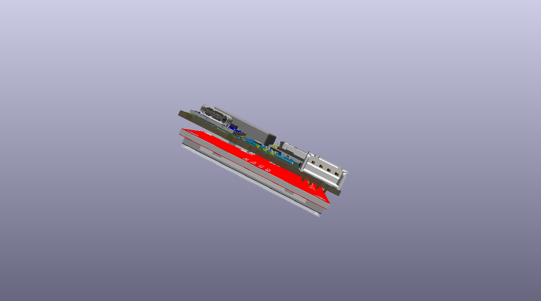
3d model of the device
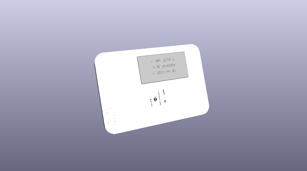
3d render, of back
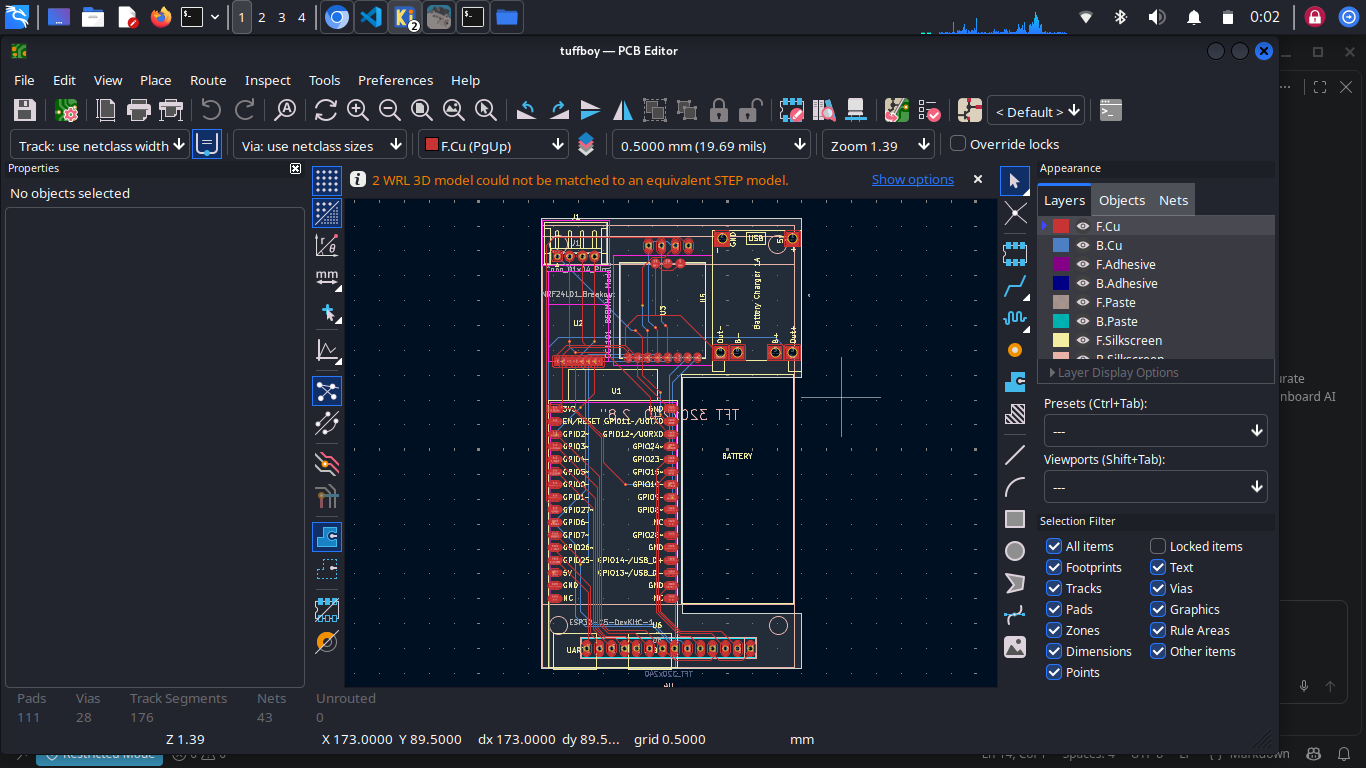
pcb layout
the 4-pin expansion connector
Schematic
So the Flipper is cool but it's not that good in base form and expensive, and things like M5 Stacks can't really do proper wifi work (absence of 5GHz). TuffBoy is my take on what that device should be:
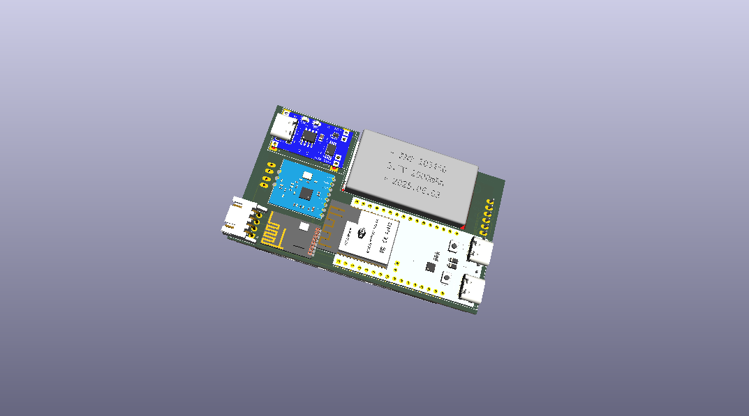
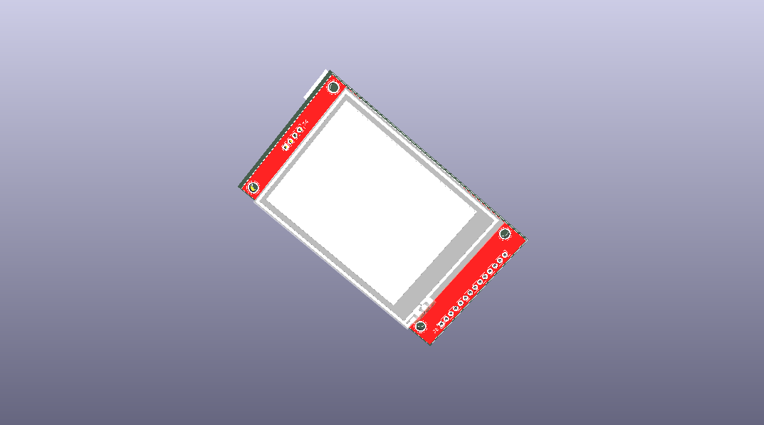
It's being made with the help of Hack Club.
To make one just see the circuit diagram images and copy it then add the script which is in the firmware folder in the esp32 c5 that's all as simple as you see. How will i make it i preffer to make this on a zero pcb first that will hlep me fix any problems with the pcb. Also if you want to know the wiring here its is:
The TuffBoy is built around an ESP32-C5 DevKit-C. The TFT, CC1101, and nRF24L01+ modules communicate with the ESP32-C5 using SPI, while the 4-pin JST-SH connector provides a UART expansion interface.
| ESP32-C5 GPIO | Connection | Function |
|---|---|---|
| GPIO 6 | SPI SCK | Shared SPI clock |
| GPIO 7 | SPI MOSI | Shared SPI data output |
| GPIO 2 | SPI MISO | Shared SPI data input |
| GPIO 10 | TFT CS | TFT chip select |
| GPIO 3 | TFT DC | TFT data/command |
| GPIO 4 | TFT RST | TFT reset |
| GPIO 5 | TFT BL | TFT backlight control |
| GPIO 8 | Touch CS | Touch controller chip select |
| GPIO 9 | Touch IRQ | Touch interrupt |
| GPIO 0 | CC1101 CS | CC1101 chip select |
| GPIO 1 | CC1101 GDO0 | CC1101 interrupt/status |
| GPIO 18 | nRF24 CSN | nRF24 chip select |
| GPIO 19 | nRF24 CE | nRF24 chip enable |
| GPIO 20 | nRF24 IRQ | nRF24 interrupt |
| GPIO 21 | UART TX | JST-SH TX |
| GPIO 22 | UART RX | JST-SH RX |
Note: GPIO numbers are the proposed firmware/pinout assignment for TuffBoy. Verify them against the exact ESP32-C5 DevKit-C board and your final PCB before manufacturing.
The TFT uses the ESP32-C5's SPI bus.
| TFT Pin | ESP32-C5 |
|---|---|
| VCC | 3.3V |
| GND | GND |
| SCK / CLK | GPIO 6 |
| MOSI / SDI | GPIO 7 |
| MISO / SDO | GPIO 2 |
| CS | GPIO 10 |
| DC / RS | GPIO 3 |
| RST | GPIO 4 |
| BL / LED | GPIO 5 |
For a typical XPT2046-style SPI touch controller:
| Touch Pin | ESP32-C5 |
|---|---|
| VCC | 3.3V |
| GND | GND |
| T_CLK | GPIO 6 |
| T_DIN | GPIO 7 |
| T_DO | GPIO 2 |
| T_CS | GPIO 8 |
| T_IRQ | GPIO 9 |
The TFT and touch controller share the SPI clock, MOSI and MISO lines. Separate chip-select lines allow the ESP32-C5 to communicate with each device independently.
The CC1101 uses the same SPI bus as the TFT and touch controller.
| CC1101 Pin | ESP32-C5 |
|---|---|
| VCC | 3.3V |
| GND | GND |
| SCK | GPIO 6 |
| MOSI / SI | GPIO 7 |
| MISO / SO | GPIO 2 |
| CSN / CS | GPIO 0 |
| GDO0 | GPIO 1 |
The CC1101 SPI bus is shared with the other SPI peripherals. Its dedicated CS pin is used to select the CC1101.
Important: The CC1101 module must be operated at the appropriate supply voltage for the specific module. Do not assume a 5V logic interface is safe.
The nRF24L01+ also shares the main SPI bus.
| nRF24L01+ Pin | ESP32-C5 |
|---|---|
| VCC | 3.3V |
| GND | GND |
| SCK | GPIO 6 |
| MOSI | GPIO 7 |
| MISO | GPIO 2 |
| CSN | GPIO 18 |
| CE | GPIO 19 |
| IRQ | GPIO 20 |
The nRF24L01+ uses the shared SPI bus while CSN and CE remain dedicated to the module.
Power note: The nRF24L01+ can be sensitive to supply noise. Place a decoupling capacitor close to the module's VCC and GND pins.
The 4-pin JST-SH connector provides power and a UART interface for an external 3.3V-compatible microcontroller or expansion board.
| JST-SH Pin | ESP32-C5 | Function |
|---|---|---|
| Pin 1 | GND | Ground |
| Pin 2 | 3.3V | VCC |
| Pin 3 | GPIO 21 | TX |
| Pin 4 | GPIO 22 | RX |
JST-SH 4-Pin
┌───────────────┐
│ 1 │ 2 │ 3 │ 4 │
└───────────────┘
  │   │   │   │
  │   │   │   └── RX
  │   │   └────── TX
  │   └────────── 3.3V
└────────────── GNDEvery flipper-clone has the same problem: you get one MCU and that's it. The TuffBoy has an expansion port for a second microcontroller:
With this we can add basically anything we like, without redesigning the main board every time. New feature = new daughter board / new firmware, not a new device.
The main focus of the software is my "wifi hack" firmware — the whole reason I started this. Wifi security testing is weirdly hard to do on existing pocket tools; the Flipper can't do it properly at all and M5 stacks are clunky for it as both lack a 5GHz radio. The goal is a firmware that makes wifi security testing easy, straight from the device UI:
obviously: use it only on networks you own or have permission to test. this is a learning tool, not a crime stick.
The flipper has a bunch of stuff mine doesn't (yet). here's the honest status on each:
| feature | flipper | tuffboy |
|---|---|---|
| sub-ghz radio | ✅ | ✅ already on board (cc1101) |
| 2.4GHz radio | ✅ | ✅ already on board (nrf24l01+) |
| wifi | ❌ | ✅ 2.4 + 5GHz — the thing flipper can't do |
| stm32 / co-processor expansion | ❌ | ✅ 4-pin connector already on board |
| IR blaster | ✅ | 🔜 needs an IR led + receiver on the next rev |
| RFID 125kHz | ✅ | 🔜 needs extra hardware |
| NFC 13.56MHz | ✅ | 🔜 needs extra hardware |
| iButton | ✅ | 🔜 1-wire on a gpio, firmware work |
| USB HID / badUSB | ✅ | 🔜 the c5 has native usb, so this is firmware-only |
| U2F security key | ✅ | 🔜 same, firmware work |
| open expansion for any 3.3v board | ❌ | ✅ |
So the plan: everything the flipper does gets added over a few board revs + firmware, and the flipper literally can't do wifi (or take a second mcu) — that's where tuffboy stays ahead.
The project currently has two firmware paths. You can either use the included TuffBoy starter/custom firmware or clone Bruce and continue from that firmware project.
The native starter firmware is located at firmware/TuffBoy/TuffBoy.ino. It is written for the ESP32-C5 Arduino framework and currently provides:
help, status, wifi, i2c, led, and more)The LED, I2C, and expansion UART pins are defined as constants at the top of the sketch because the final pin mapping may change between board revisions. The sketch uses the ESP32 Arduino framework APIs and the built-in Wire and WiFi libraries.
The project also contains custom firmware developed specifically for TuffBoy, which will be used as the project continues beyond the initial hardware testing stage.
The firmware/Bruce Firmware Cloner.py script downloads the Bruce firmware into a Bruce/ directory. It requires Python 3.7 or newer. Git is used by default, or the --zip option can download an archive without Git.
# Clone Bruce into the current directory
python3 "firmware/Bruce Firmware Cloner.py"

# Shallow clone into a chosen directory
python3 "firmware/Bruce Firmware Cloner.py" -d ~/projects --depth 1

# Download Bruce as a ZIP archive instead of using Git
python3 "firmware/Bruce Firmware Cloner.py" -d ~/projects --zip
Useful options are --branch for a specific branch and --deps to install the Python build dependencies used by Bruce. After cloning, follow Bruce's own board and build instructions in its repository.
The PCB uses 3D CAD models of the individual components mainly for visualisation of the PCB and complete assembly.
The individual component CAD models used in the PCB 3D model were downloaded from GrabCAD. These models are used to represent the physical components and their approximate placement in the complete assembly.
The TuffBoy cover/enclosure was made according to the requirements of the project and the completed PCB. The cover was made externally according to the required dimensions, component placement and mechanical requirements, and the STEP file was provided for use with the project.
tuffboy/          the kicad 10 project (sch + pcb)
tuffboy.pretty/   third-party libs (xiaosymbols, ssd1306 footprints etc)
CAD/              step models (esp32-c5, nrf24l01, cc1101, oleds, 603040 battery)
images/           pcb renders + board pics
firmware/         TuffBoy custom firmware and Bruce cloning script
BOM.csv           bill of materials
Front Housing.step
Rear Housing.step
assembly(full)-reduced.stl
tuffboy(without case)-reduced.stl
Open tuffboy/tuffboy.kicad_pro in kicad 10 and you're good.
| Component | Qty | Description | Unit Price | Total |
|---|---|---|---|---|
| ESP32-C5-DevKitC-1 | 1 | ESP32-C5 Wi-Fi 6/6E development board | ₹1,339 | ₹1,339 |
| NRF24L01 Breakout | 1 | nRF24L01+ 2.4GHz RF transceiver module | ₹113 | ₹113 |
| CC1101-868MHz Module | 1 | CC1101 868/915MHz Sub-GHz RF module | ₹247 | ₹247 |
| TFT 320x240 | 1 | 2.8" TFT LCD 320×240 touch display | ₹959 | ₹959 |
| TP4056 | 1 | TP4056 Type-C Li-ion battery charging module | ₹16 | ₹16 |
| 18650 Li-Ion Battery | 4 | 3.7V Li-Ion battery | ₹122 | ₹488 |
| UART Connector | 1 | 4-pin JST connector for expansion/UART | ₹2 | ₹2 |
| Zero PCB | 5 | Perfboard used for initial PCB prototyping | ₹29 | ₹145 |
| Soldering Kit | 1 | Adjustable soldering station/kit | ₹1,399 | ₹1,399 |
| Jumper Cables | 2 | Jumper wire sets for prototyping and wiring | ₹159 | ₹318 |
| Soldering Stand | 1 | Helping-hand soldering stand with magnifier | ₹694 | ₹694 |
| Soldering Wick | 2 | Desoldering braid | ₹18 | ₹36 |
| JST Female Connector | 2 | 4-pin JST connector with wires | ₹13 | ₹26 |
| Total | ₹5,782 |
Total: ₹5,782 INR
Approximately: $60.27 USD
Prices are approximate and may change depending on availability, shipping, taxes, and seller pricing. Buy links are in BOM.csv
| Image | Description |
|---|---|
| 3D model of the device |
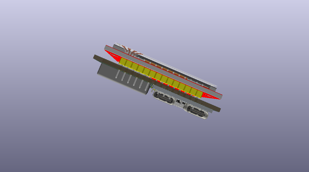 | USB-C connector detail |
| PCB layout |
| Schematic |
| Top view of the device |
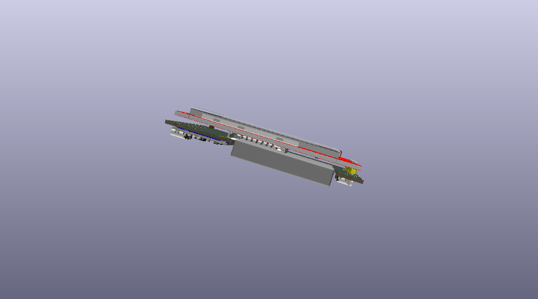 | SD card slot |
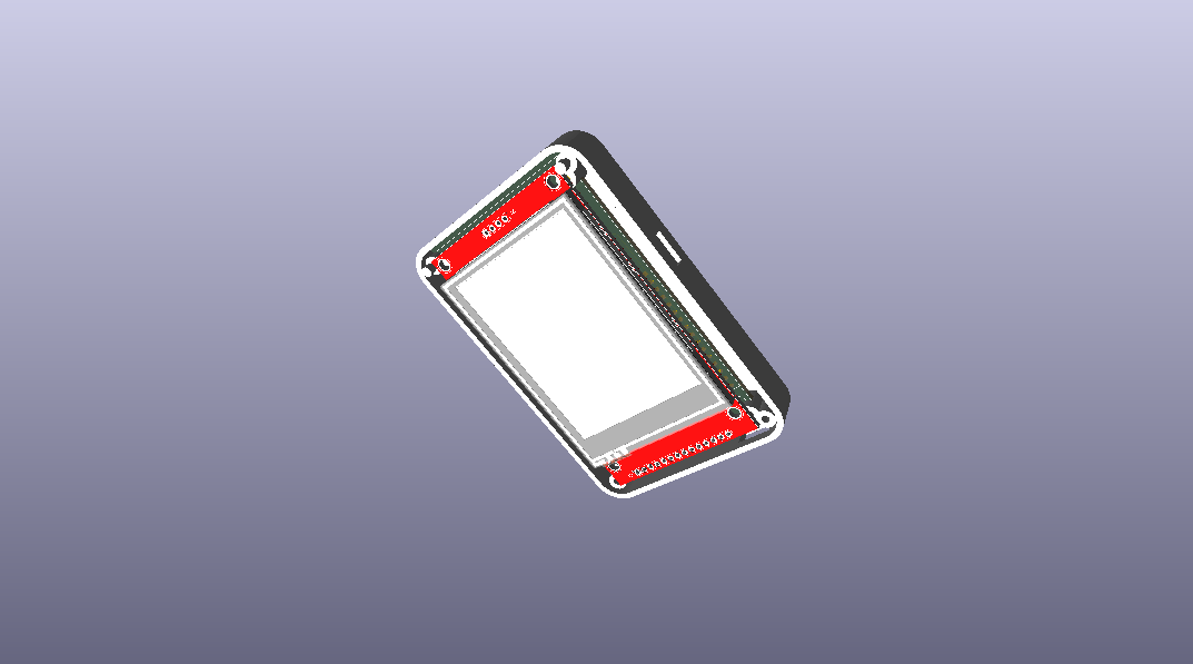 | Back cover |
| 3D render of back |
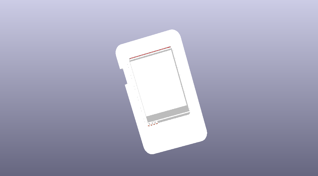 | Top cover |
| 4-pin JST expansion connector |
| Back view of the device |
hardware: PCB completed · software: custom firmware in development · last updated Sep 2026
| Qty | Value | Footprint | References |
|---|---|---|---|
| 1 | CC1101-868MHz-Module | tuffboy:CC1101-868MHz-Module | U3 |
| 1 | Conn_01x04_Pin | tuffboy:JST_EH_S4B-EH_1x04_P2.50mm_Horizontal | J1 |
| 1 | ESP32-C5-DevKitC-1 | tuffboy:ESP32-C5-DevKitC-1 | U1 |
| 1 | NRF24L01_Breakout | tuffboy:NRF24L01-SMD | U2 |
| 1 | TFT_320x240 | tuffboy:TFT-320x240 | U4 |
| 1 | ~ | tuffboy:TP4056-18650 | U5 |
| 1 | ~ | tuffboy:battery | U6 |
byrantech/laptop
anyon_e, a highly integrated, high end, open source laptop. Attempt the impossible.


AxxAxx/AxxSolder
STM32 Based soldering station for JBC cartridges, 9-24 VDC and USB-PD power


jamro/tiny-engineer
A small desktop robot that brings an AI coding assistant to life, physically acting out when it reads files, thinks, writes code, and finishes work.

hoglet67/RGBtoHDMI
Bare-metal Raspberry Pi project that provides pixel-perfect sampling of Retro Computer RGB/YUV video and conversion to HDMI

It measures 52.5 × 90.5 mm and has 2 copper layers, 1.6 mm thick.
7 parts. The full list of its parts is on this page, with links to each part's symbol and footprint where PCBKit's library has them.
From the ishantdahiya1501-ctrl/tuffboy repository on GitHub, at the commit this page was made from: the board is tuffboy/tuffboy.kicad_pcb and its schematic tuffboy/tuffboy.kicad_sch. PCBKit opens the board in the browser, with nothing to install.
Its repository states no licence, so its author keeps all rights: ask ishantdahiya1501-ctrl before reusing the design.