2 layers89.9 × 42.7 mm
Monolith
Monolith-BCI/Trillium-PCB
We're a group of teens working on creating a BCI PCB to start running our own experiments on noise filtering, signal processing speed, and data collection.
89 parts5

 Ishaka-M26/EEG-Platform
A custom multichannel EEG acquisition platform for exploring real-time EEG processing and closed-loop neurotechnology.
Eeg frontend is an open-source printed circuit board by Ishaka-M26, from the Ishaka-M26/EEG-Platform repository on GitHub. It is a 4-layer board of 60 × 67.4 mm with 79 parts on 90 nets, routed with 1,200 tracks and 80 vias.
It is built around the TPD4E1B06DCKR-TP, TPS72325DBV and DMP3099L. Its parts include 21 capacitors, 11 resistors, 11 ICs, 10 connectors and 1 transistor.


A custom multichannel EEG acquisition platform for exploring real-time EEG processing and closed-loop neurotechnology.
The ADS1299 acquires data at 250 samples per second (SPS). The processor uses every 10th sample to calculate the peak-to-peak amplitude of Channel 1 over a 1-second window (25 samples). When the peak-to-peak amplitude exceeds a threshold of 800 ADC counts, an LED is activated and held on for approximately 5 seconds.
In this test, a manually performed eye blink produced a transient increase in the measured range and triggered the LED in real time.
https://github.com/user-attachments/assets/f996c3a0-e510-41c0-a689-779db01b0a72
For the blink detection experiment, Channel 1 was configured to measure the differential voltage between Fp1 and A1, following the International 10–20 electrode placement system.
The frontal electrode placement allows the system to capture voltage transients associated with eye blinks. These transients are primarily related to ocular activity (EOG artifacts) rather than cortical EEG activity.
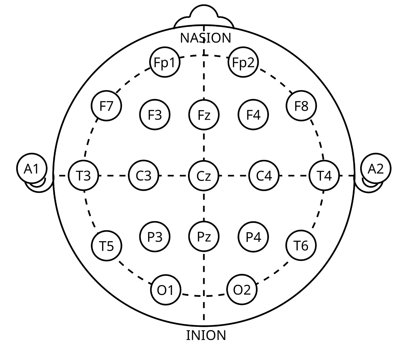
Electrode placement for blink detection based on the International 10–20 system.
CH1 min=-23961 max=-23366 range=595  LED=0
CH1 min=-24158 max=-23965 range=193  LED=0
CH1 min=-24212 max=-22453 range=1759 LED=1  <-- blink detected
CH1 min=-24368 max=-24239 range=129  LED=1
CH1 min=-24333 max=-24226 range=107  LED=1
CH1 min=-24637 max=-24358 range=279  LED=1
The third window exceeded the detection threshold: 1759 > 800
and triggered the LED. The LED remains on for approximately 500 ms after detection, which is why LED=1 continues in the following windows even though their ranges fall below the threshold.
As a next step toward real-time EEG-based brain-state estimation, I implemented FFT-based spectral analysis on the Zynq processing system.
EEG signals were recorded from an occipital channel under eyes-open (EO) and eyes-closed (EC) conditions. Power spectral density (PSD) was calculated using a 256-point Hann-windowed FFT at a sampling rate of 250 SPS.
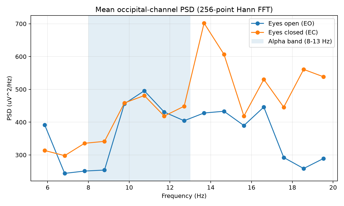
Mean PSD under eyes-open and eyes-closed conditions. The shaded region indicates the alpha band (8–13 Hz).
The preliminary results show differences in spectral power between the two conditions. However, a clear eyes-closed increase within the alpha band was not observed. Larger differences appeared at frequencies above 13 Hz.
Further validation of electrode contact, signal quality, and spectral characteristics is needed before attributing these differences to cortical alpha activity.
For the alpha-band experiment, Channel 1 was configured to measure the differential voltage between the left occipital region and the left ear, based on the International 10–20 electrode placement system.
Ten20 conductive paste was applied to improve electrode contact with the scalp.

Ten20 conductive paste used for electrode contact.
The occipital electrode placement was selected to investigate alpha-band activity (8–13 Hz), which is commonly more prominent over posterior brain regions during eyes-closed conditions.
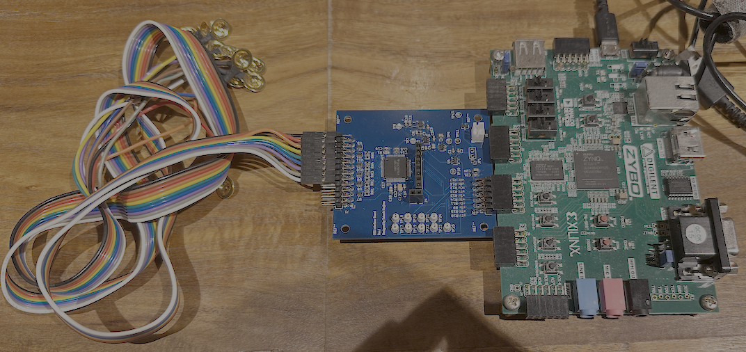
Prototype setup: EEG electrodes, custom ADS1299 interface board, and Zybo Zynq-7000.
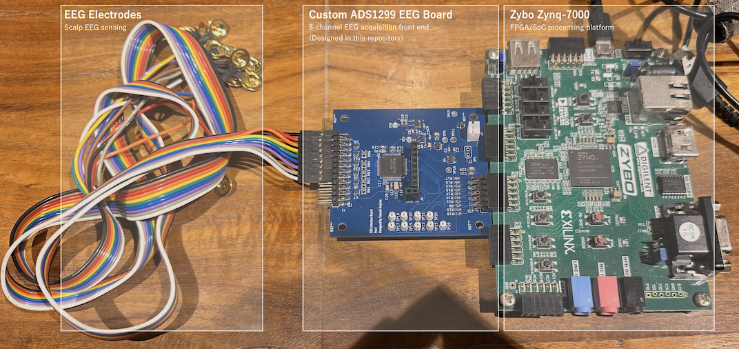
Hardware connections and major components of the current prototype.
A custom EEG acquisition platform for real-time neural signal measurement and future closed-loop neurostimulation research.
The system is built around a custom ADS1299-based EEG frontend and a Zynq-based processing platform.
The current focus is reliable multichannel EEG acquisition, real-time data transfer, and system-level validation from analog input to digital processing.
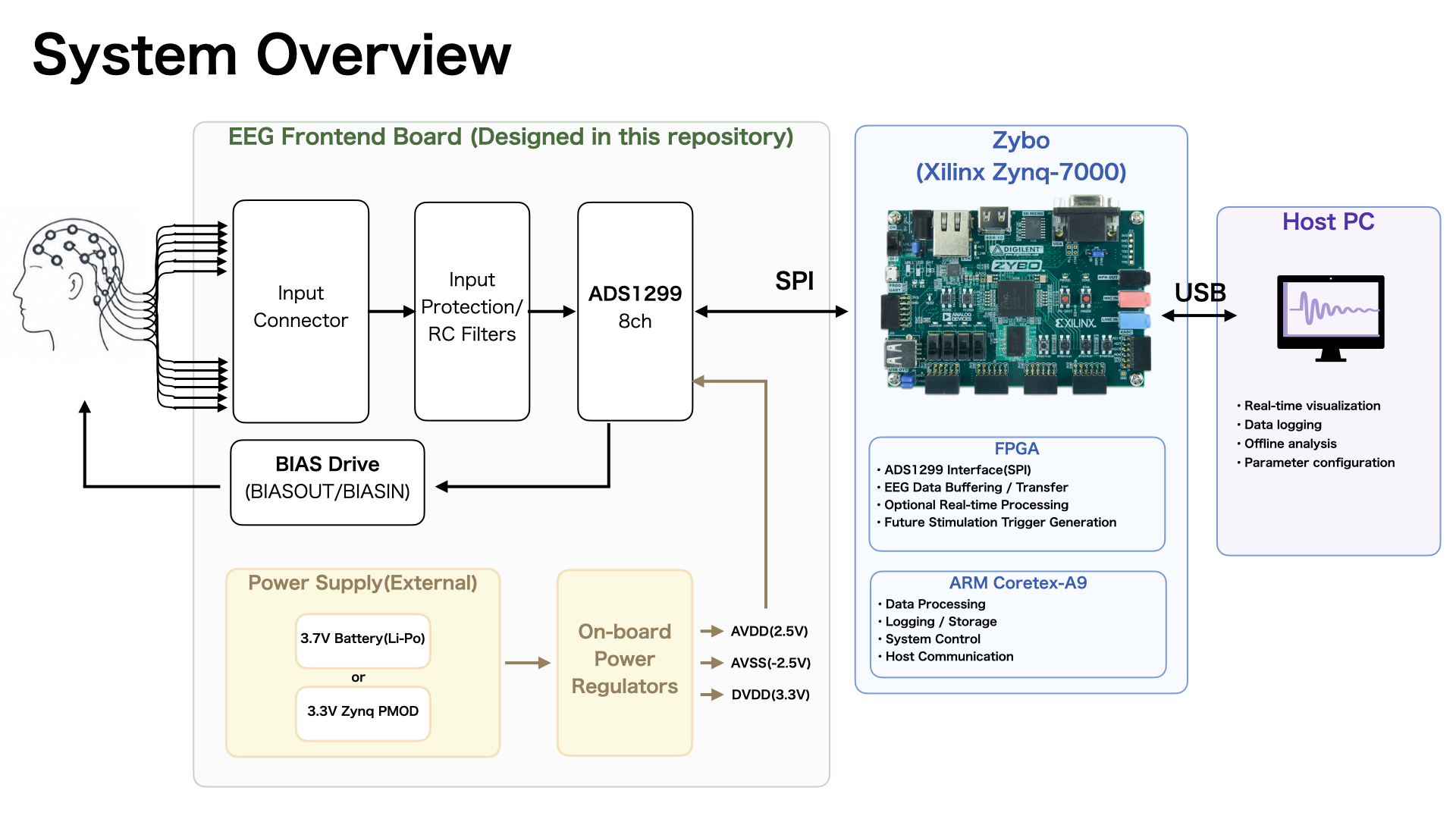
The platform consists of:
Custom EEG Frontend Board
Zybo Z7 / Zynq Platform
Host PC
The long-term goal is to extend this platform toward a closed-loop architecture in which brain-state information is estimated in real time and used to control non-invasive stimulation.
The EEG frontend board is designed specifically for this project.
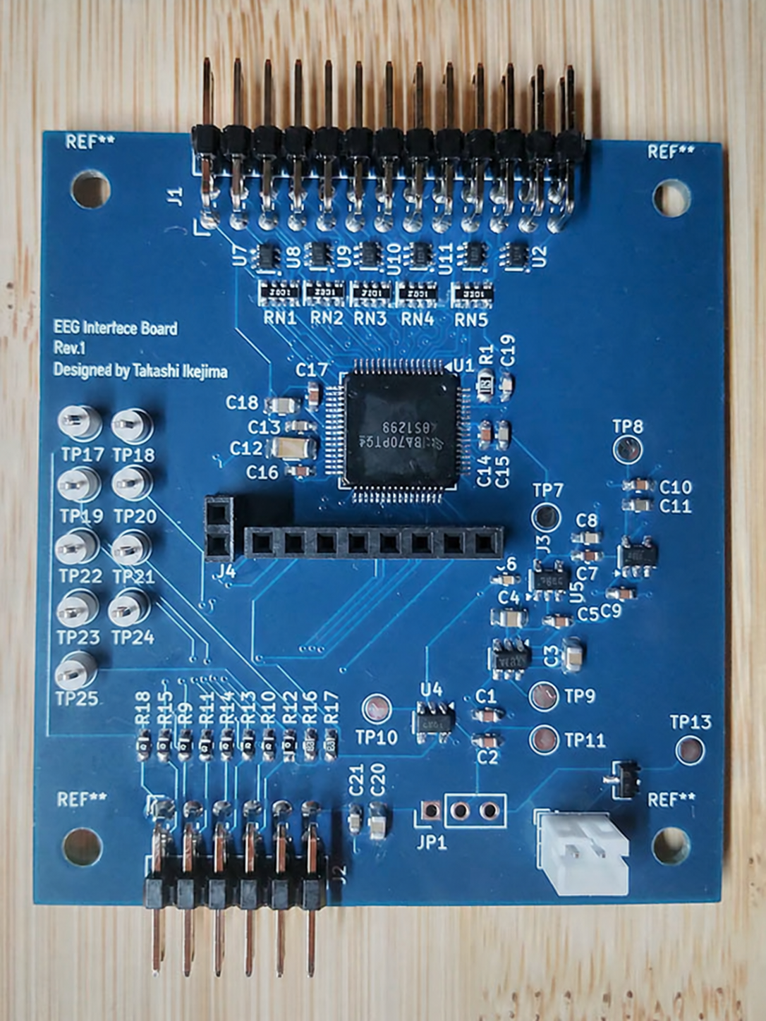
It is based on the ADS1299, an 8-channel, 24-bit analog front end for biopotential measurement.
The board integrates EEG input protection, analog acquisition, power regulation, and the digital interface required for connection to the Zynq platform.
The KiCad schematic and PCB design files are available in:
hardware/kicad/eeg-frontend/The ADS1299 is configured directly from FPGA logic over SPI. The initialization sequence was verified on hardware using Vivado ILA.
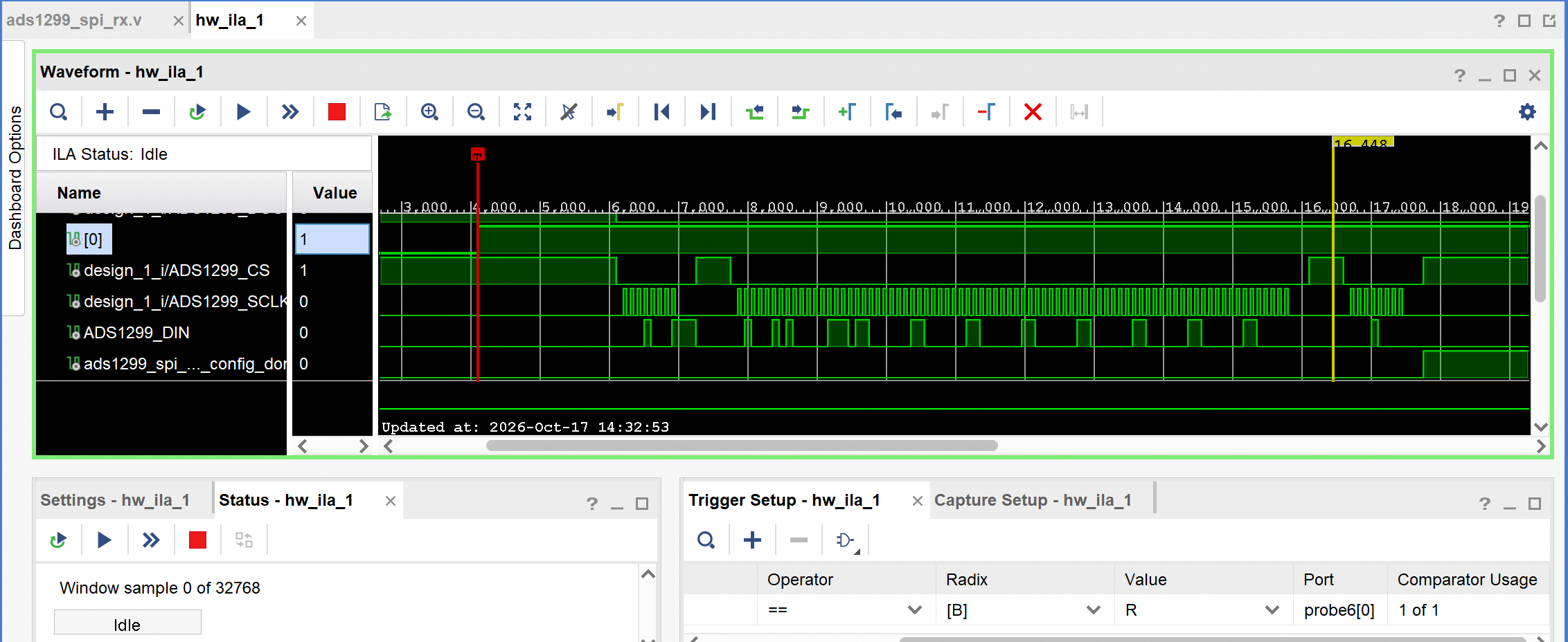
Vivado ILA capture of the ADS1299 initialization sequence. SPI chip-select, clock, and DIN activity are monitored in the PL, and config_done is asserted after the initialization sequence completes.
| Step | SPI command | Purpose |
|---|---|---|
| 1 | SDATAC (0x11) | Stop continuous data mode before register writes |
| 2 | WREG CONFIG3 | Enable internal reference |
| 3 | WREG CH1SET..CH8SET | Configure channel gain and input mode |
| 4 | RDATAC (0x10) | Resume continuous data output |
The project is being developed in stages:
The initial objective is not to build a complete clinical neurostimulation device, but to establish a reliable hardware and software platform for real-time EEG-based neural interface research.
eeg-platform/
├── docs/
│   └── images/
│       ├── eeg-frontend-3d.png
│       ├── eeg-frontend-pcb.png
│       └── system_overview.png
│
├── hardware/
│   └── kicad/
│       ├── eeg-frontend/
│       └── reference_design/
│
└── README.md| Qty | Value | Footprint | References |
|---|---|---|---|
| 8 | 0 | Resistor_SMD:R_0603_1608Metric_Pad0.98x0.95mm_HandSolder | R9, R10, R11, R12, R13, R14, R15, R18 |
| 6 | 2.2uF | Capacitor_SMD:C_0603_1608Metric_Pad1.08x0.95mm_HandSolder | C1, C2, C5, C7, C9, C10 |
| 6 | TPD4E1B06DCKR | Package_TO_SOT_SMD:SOT-363_SC-70-6 | U2, U7, U8, U9, U10, U11 |
| 5 | 1000pF | myLibrary:C_Array_Convex_4x0612 | CN3, CN4, CN5, CN6, CN7 |
| 5 | R_Array_4 | Resistor_SMD:R_Cat16-4 | RN1, RN2, RN3, RN4, RN5 |
| 4 | 10uF | Capacitor_SMD:C_0805_2012Metric_Pad1.18x1.45mm_HandSolder | C3, C4, C18, C20 |
| 4 | 1uF | Capacitor_SMD:C_0603_1608Metric_Pad1.08x0.95mm_HandSolder | C13, C14, C16, C17 |
| 2 | 0.1uF | Capacitor_SMD:C_0603_1608Metric_Pad1.08x0.95mm_HandSolder | C15, C21 |
| 2 | 10K | Resistor_SMD:R_0603_1608Metric_Pad0.98x0.95mm_HandSolder | R16, R17 |
| 2 | 10uF | Capacitor_SMD:C_0603_1608Metric_Pad1.08x0.95mm_HandSolder | C8, C11 |
| 1 | 0.01uF | Capacitor_SMD:C_0603_1608Metric_Pad1.08x0.95mm_HandSolder | C6 |
| 1 | 100uF | Capacitor_SMD:C_1206_3216Metric_Pad1.33x1.80mm_HandSolder | C12 |
| 1 | 1M | Resistor_SMD:R_0805_2012Metric_Pad1.20x1.40mm_HandSolder | R1 |
| 1 | 1nF | Capacitor_SMD:C_0603_1608Metric_Pad1.08x0.95mm_HandSolder | C19 |
| 1 | ADS1299 | Package_QFP:TQFP-64_10x10mm_P0.5mm | U1 |
| 1 | Conn_01x02 | Connector_PinSocket_2.54mm:PinSocket_1x02_P2.54mm_Vertical | J4 |
| 1 | Conn_01x02 | Connector_JST:JST_PH_B2B-PH-K_1x02_P2.00mm_Vertical | J5 |
| 1 | Conn_01x08 | Connector_PinSocket_2.54mm:PinSocket_1x08_P2.54mm_Vertical | J3 |
| 1 | Conn_02x06_Top_Bottom | myLibrary:PinHeader_2x06_P2.54mm_Horizontal_pmod | J2 |
| 1 | DMP3099L | Package_TO_SOT_SMD:SOT-23 | Q1 |
| 1 | EEG Connector | myLibrary:PinHeader_2x13_P2.54mm_Horizontal_mirror | J1 |
| 1 | Jumper_3_Open | Connector_PinHeader_2.54mm:PinHeader_1x03_P2.54mm_Vertical | JP1 |
| 1 | LM2664M6/NOPB | Package_TO_SOT_SMD:SOT-23-6 | U3 |
| 1 | MCP1754T-3302E/OT | Package_TO_SOT_SMD:SOT-23-5 | U4 |
| 1 | TLV70025_SOT23-5 | Package_TO_SOT_SMD:SOT-23-5 | U6 |
| 1 | TPS72325DBV | Package_TO_SOT_SMD:SOT-23-5 | U5 |
| 1 | TP_3V_ENABLE | TestPoint:TestPoint_Pad_D2.0mm | TP10 |
| 1 | TP_AVDD | TestPoint:TestPoint_Pad_D2.0mm | TP8 |
| 1 | TP_AVSS | TestPoint:TestPoint_Pad_D2.0mm | TP7 |
| 1 | TP_CS | TestPoint:TestPoint_Loop_D2.50mm_Drill1.0mm | TP19 |
| 1 | TP_CS2 | TestPoint:TestPoint_Loop_D2.50mm_Drill1.0mm | TP25 |
| 1 | TP_DRDY | TestPoint:TestPoint_Loop_D2.50mm_Drill1.0mm | TP23 |
| 1 | TP_DVDD | TestPoint:TestPoint_Pad_D2.0mm | TP9 |
| 1 | TP_MISO | TestPoint:TestPoint_Loop_D2.50mm_Drill1.0mm | TP24 |
| 1 | TP_MOSI | TestPoint:TestPoint_Loop_D2.50mm_Drill1.0mm | TP18 |
| 1 | TP_PWDN | TestPoint:TestPoint_Loop_D2.50mm_Drill1.0mm | TP21 |
| 1 | TP_RESET | TestPoint:TestPoint_Loop_D2.50mm_Drill1.0mm | TP22 |
| 1 | TP_SCLK | TestPoint:TestPoint_Loop_D2.50mm_Drill1.0mm | TP17 |
| 1 | TP_START | TestPoint:TestPoint_Loop_D2.50mm_Drill1.0mm | TP20 |
| 1 | TP_VIN_BAT | TestPoint:TestPoint_Pad_D2.0mm | TP13 |
| 1 | TP_VIN_SYS | TestPoint:TestPoint_Pad_D2.0mm | TP11 |
The 75 most common of 79 parts.
It measures 60 × 67.4 mm and has 4 copper layers, 1.6 mm thick.
79 parts, built around the TPD4E1B06DCKR-TP, TPS72325DBV and DMP3099L. The full list of its parts is on this page, with links to each part's symbol and footprint where PCBKit's library has them.
From the Ishaka-M26/EEG-Platform repository on GitHub, at the commit this page was made from: the board is hardware/kicad/eeg-frontend/eeg-frontend.kicad_pcb and its schematic hardware/kicad/eeg-frontend/ads1299.kicad_sch. PCBKit opens the board in the browser, with nothing to install.
Its repository states no licence, so its author keeps all rights: ask Ishaka-M26 before reusing the design.
Monolith-BCI/Trillium-PCB
We're a group of teens working on creating a BCI PCB to start running our own experiments on noise filtering, signal processing speed, and data collection.


ppolGTMonster/RobustEEG_forUHFMRI
Hardware for an Open Source EEG usable in high magnetic Fields

CGrassin/biosignals
Board for the acquisition of bio-potentials (EMG, ECG, EEG, etc.).

node9909/Graduation-project-files
design of a HD-SEMG system, using ads1298, Arduino DUE, ST32F4, INA333 adn AD8232

yelabb/pcbfork
A browser sandbox testing if LLMs can optimize KiCad board layouts by treating the AI as an untrusted proposal generator for low-noise biosignal PCBs

aaronadamski/brainsolutions-eegboard
EEG Prototype Board for UCI Senior Design
