4 layers90.3 × 98 mm
RPi Pico W A4988 control board
Ironman-007/PCBPT
This is a system that can help directly connect the schematic of the PCB design with test equipment (oscilloscope. etc,).
93 parts11

 Ironman-007/PCBPT11
This is a system that can help directly connect the schematic of the PCB design with test equipment (oscilloscope. etc,).
PWR module is an open-source printed circuit board by Ironman-007, from the Ironman-007/PCBPT repository on GitHub. It is a 2-layer board of 34.6 × 34.6 mm with 5 parts on 5 nets.
It is built around the 46223C. Its parts include 2 inductors and 1 connector.
This is a system that can help directly connect the schematic of the PCB design with test equipment (oscilloscope. etc,). When doing PCB debugging, we would need to use our hands to hold the oscilloscope probes, and our hands can not be that precise and table. Sometimes our hands are not enough, and we need to go from schematic and PCB layout back and forth to find a proper pad for the signal and place a probe on it.
The PCBPT connects the Sch with the oscilloscope. The user can choose a signal they want to check on the Sch, and the system will choose a proper pad and place a probe on the pad. Then the user can just check the output from the oscilloscope. All the user needs to do is select signals from Sch and check the output.
The first version of PCBPT is here: https://www.media.mit.edu/projects/pcb-probe-tester/overview/
It's very rough. The machine design is not that perfect. The motor I used is 28BYJ-48. It's very slow. The software is not that good, either. I have a separate GUI for the signal choosing. However, what I want is to choose the signal from the EDA, or make a GUI with the Sch and choose the signal from the SCH.
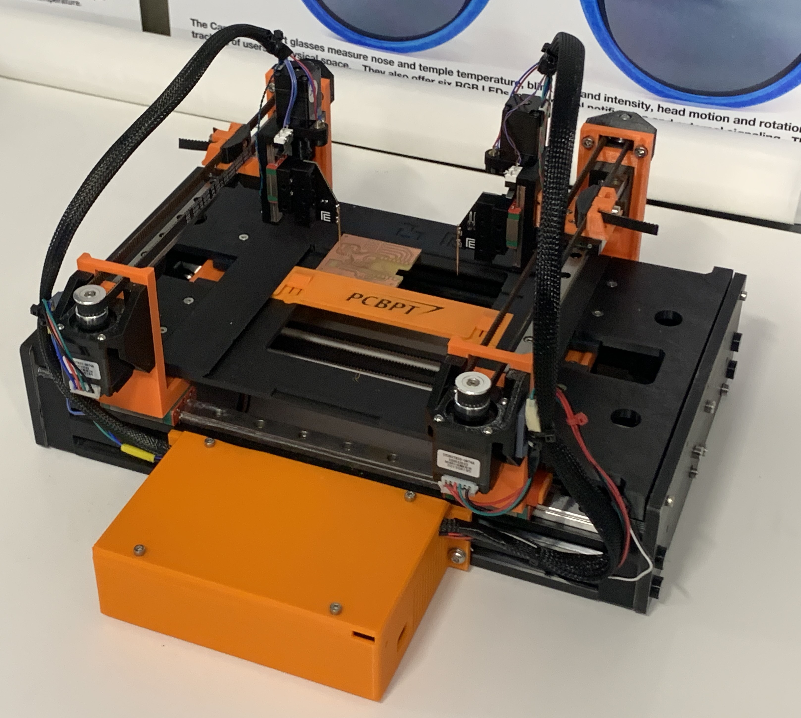
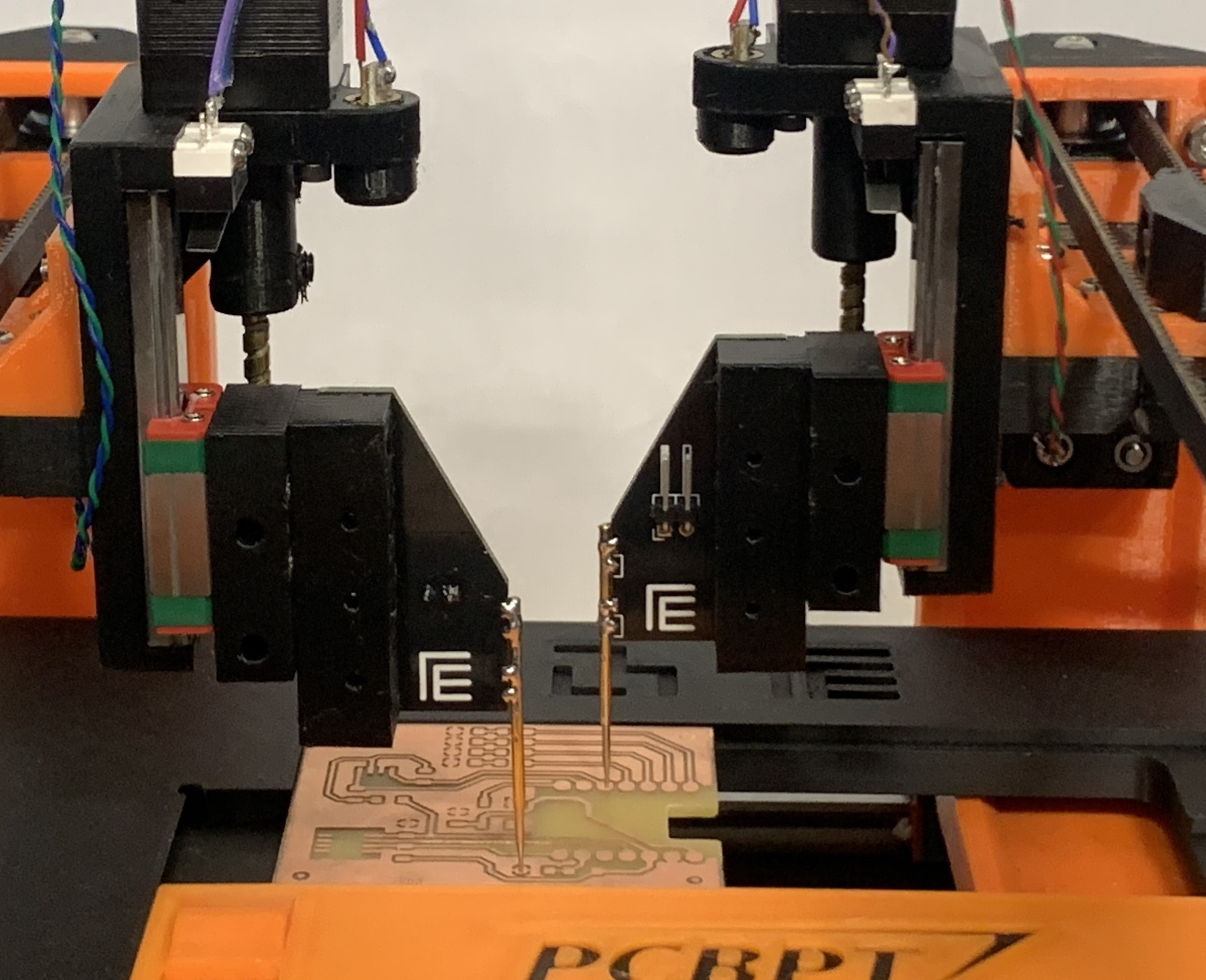
The new machine design (I really love the Prusa color!).
The first version of the main control board is a modular design. Each module can control a stepper motor and a servo. Each module is an RP2040 XIAO + A4988 stepper driver. The host is an ESP32 module.
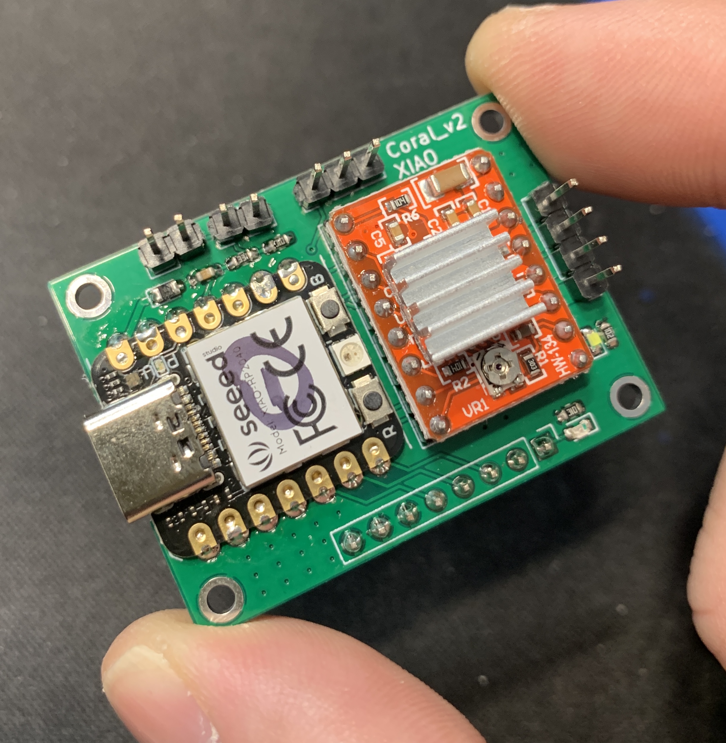
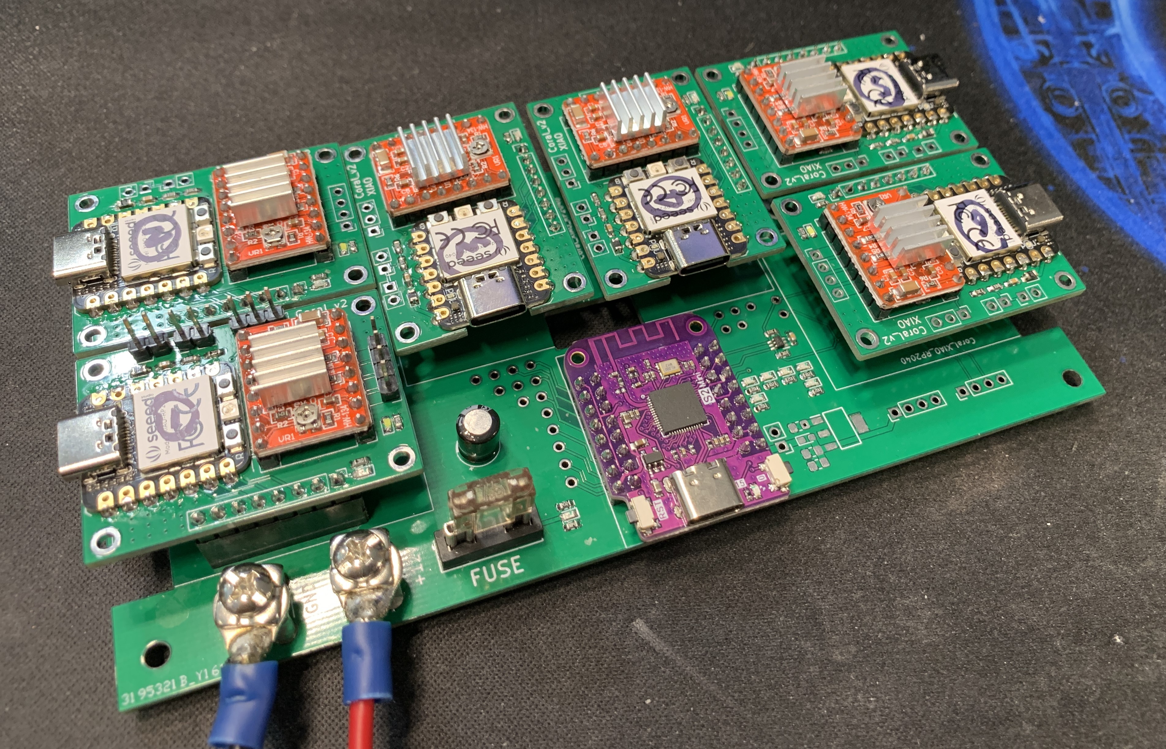
All stepper control modules are connected with the ESP32 module with I2C. The Host runs CircuitPython and is responsible for handling commands from the GUI and sending commands to each stepper control module. This design is unnecessarily complicated compared with the function of the machine.
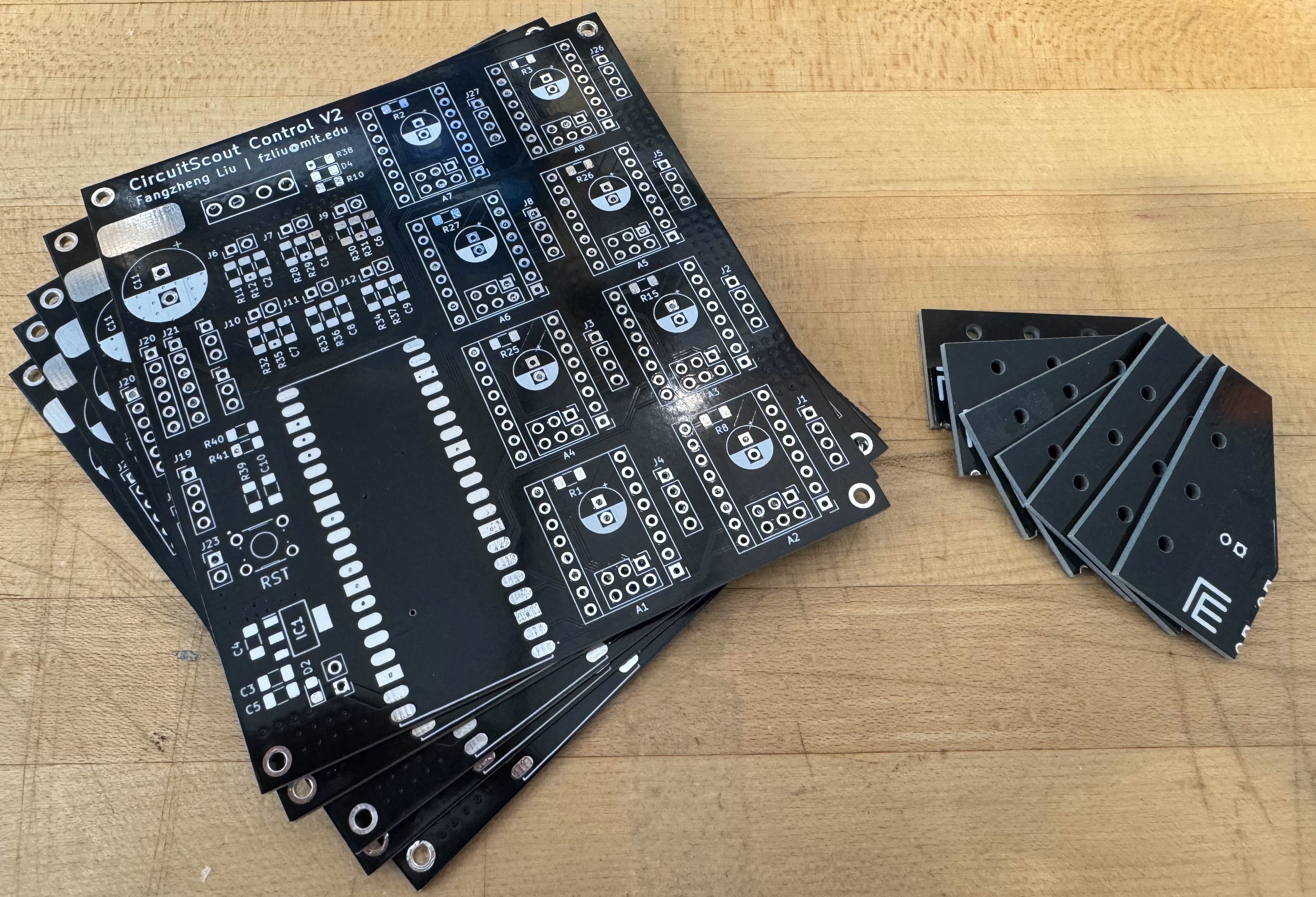
The second version of the main control board is a single board. One RPi Pico W module + 6 A4988 driver modules. The probes are in vertical motion, and each probe is a triangle PCB board with a pogo pin soldered on the edge.
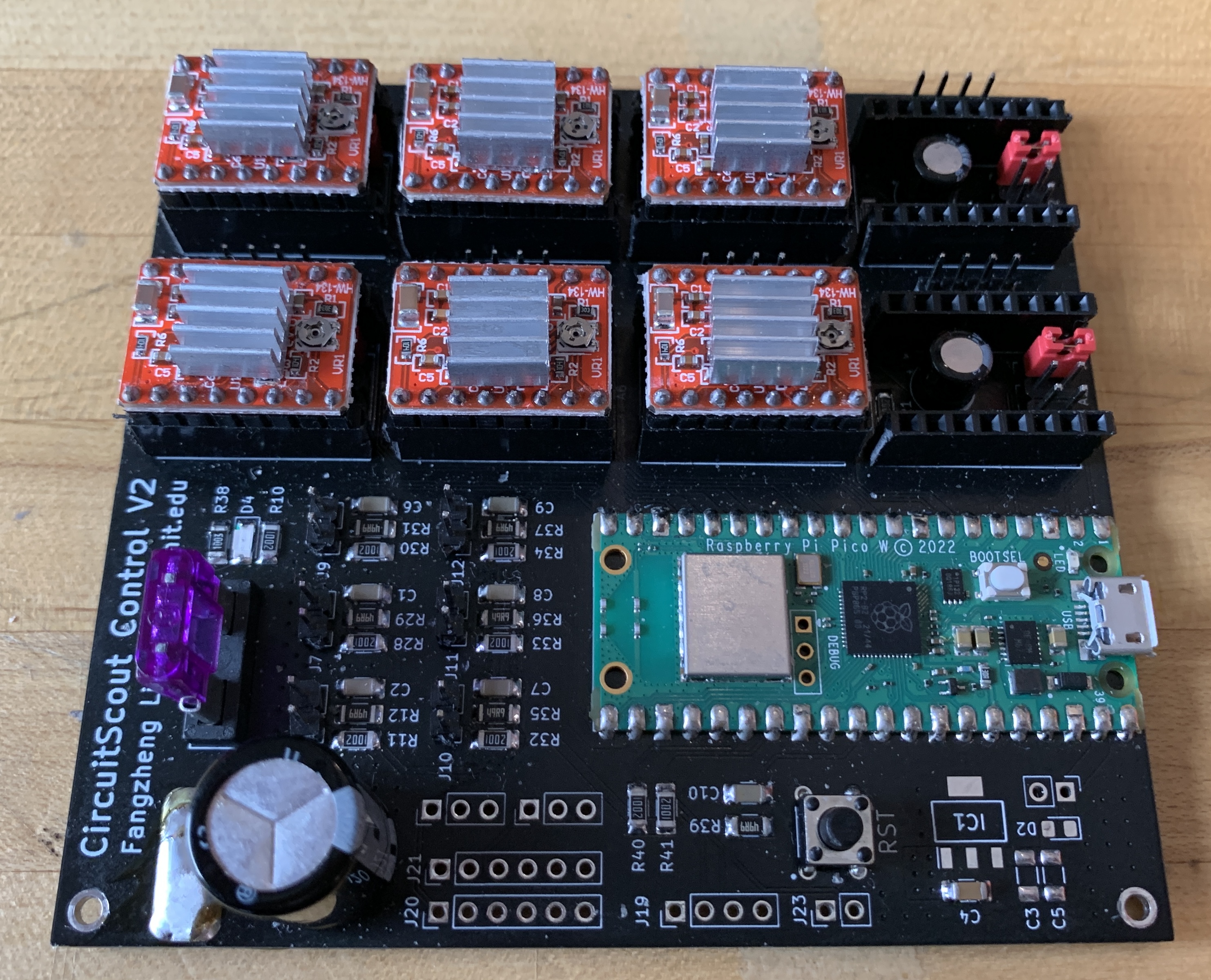
I use the PCBWay service for both the second version of the main control board and the triangle probe PCB board. The quality is good and the production is very fast.
| Qty | Value | Footprint | References |
|---|---|---|---|
| 2 | 46223C | Mylib:INDPM7373X455N | L1, L2 |
| 2 | M2 | MountingHole:MountingHole_2.2mm_M2 | H2, H3 |
| 1 | DCJ200-05-A-XX-X_REVA | Mylib:GCT_DCJ200-05-A-XX-X_REVA | J1 |
Ironman-007/PCBPT
This is a system that can help directly connect the schematic of the PCB design with test equipment (oscilloscope. etc,).

Ironman-007/PCBPT
This is a system that can help directly connect the schematic of the PCB design with test equipment (oscilloscope. etc,).

Ironman-007/PCBPT
This is a system that can help directly connect the schematic of the PCB design with test equipment (oscilloscope. etc,).

Ironman-007/PCBPT
This is a system that can help directly connect the schematic of the PCB design with test equipment (oscilloscope. etc,).

Ironman-007/PCBPT
This is a system that can help directly connect the schematic of the PCB design with test equipment (oscilloscope. etc,).


joypad-ai/joypad-os
Universal controller firmware for building adapters, dongles, and custom controllers.

OLIMEX/OLINUXINO
OLINUXINO is Open Source / Open Hardware, low cost from EUR 24 Linux Industrial grade Single Board Computer capable to operate -25+85C

jamro/tiny-engineer
A small desktop robot that brings an AI coding assistant to life, physically acting out when it reads files, thinks, writes code, and finishes work.

hackclub/OnBoard
💡 Join 1,000 teenagers and make your first PCB with a $100 grant!


Luos-io/luos_engine
Open-source and real-time orchestrator for cyber-physical-systems, to easily design, test and deploy embedded applications and digital twins.
It measures 34.6 × 34.6 mm and has 2 copper layers, 1.6 mm thick.
5 parts, built around the 46223C. The full list of its parts is on this page, with links to each part's symbol and footprint where PCBKit's library has them.
From the Ironman-007/PCBPT repository on GitHub, at the commit this page was made from: the board is PCBPT_V3/PCB/PWR_module/PWR_module.kicad_pcb and its schematic PCB/PCBPT/PCBPT.kicad_sch. PCBKit opens the board in the browser, with nothing to install.
Its repository states no licence, so its author keeps all rights: ask Ironman-007 before reusing the design.