2 layers
Accoustic Sensing Node
irocobble/CA_LR_ES
Open-source ESP32-S3 edge computing module with LoRa, GPS, external flash, MicroSD, and expansion support for long-range IoT applications.
105 parts

 irocobble/CA_LR_ES
Open-source ESP32-S3 edge computing module with LoRa, GPS, external flash, MicroSD, and expansion support for long-range IoT applications.
Accoustic Sensing Node is an open-source printed circuit board by irocobble, from the irocobble/CA_LR_ES repository on GitHub. It is a 4-layer board of 50 × 75 mm with 129 parts on 161 nets, routed with 1,130 tracks and 560 vias.
It is built around the AP63203WU, MAX-M10S and MPU-9250, with the USBLC6-4SC6, MMBT3904 and BAT54 among its other parts. Its parts include 53 capacitors, 31 resistors, 12 diodes, 9 ICs and 7 inductors. It belongs with the radio and wireless boards and the ESP32 boards of this library.


Team: Aninda Majumdar (@irocobble) · Subham Basak · Kartik Kajra
A two-board, field-deployable acoustic sensor for search-and-rescue. The node is placed in rubble or debris and listens for signs of a trapped person (voice, tapping, banging). It works out which direction the sound came from and sends a GPS-tagged alert over LoRa to a rescue dashboard.
Searching collapsed structures is a race against time, and the hardest question is where to dig. Instead of sending people onto unstable rubble to listen, the node sends the ears in first.
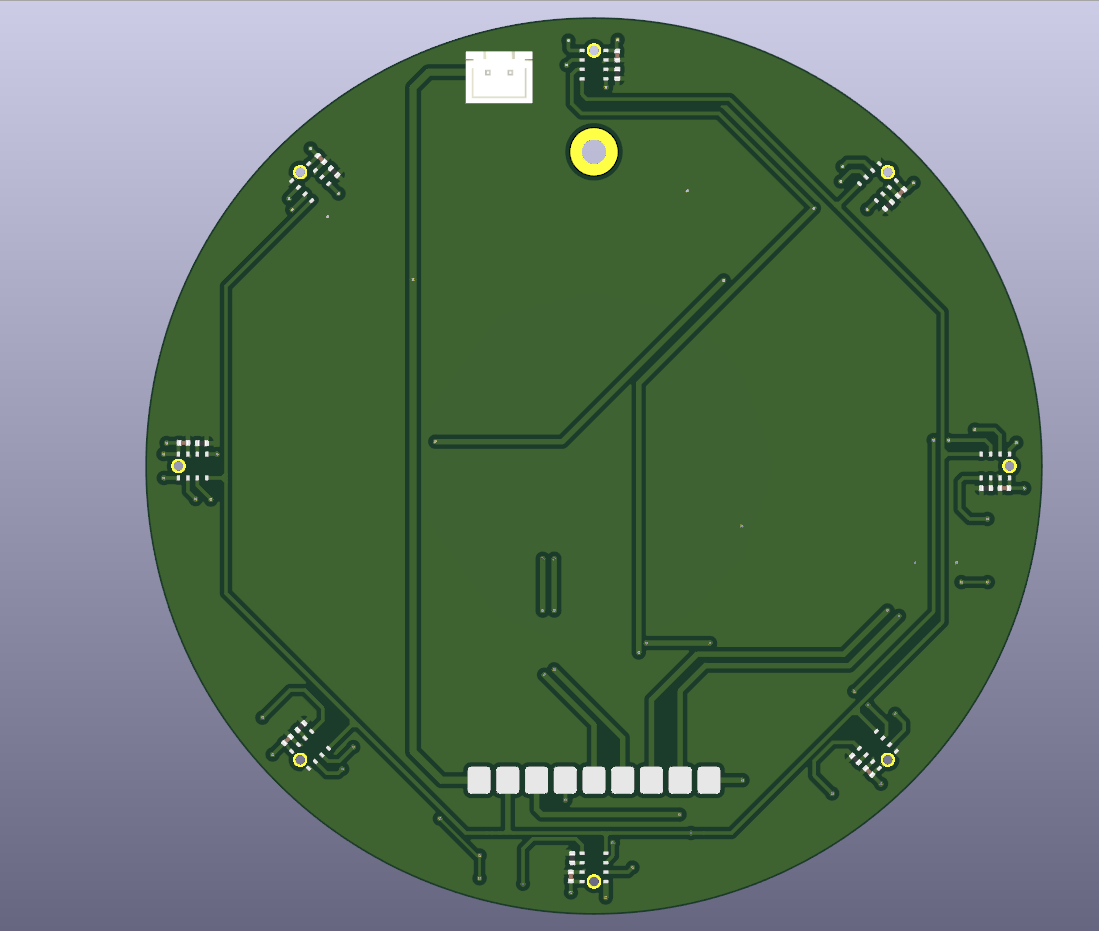
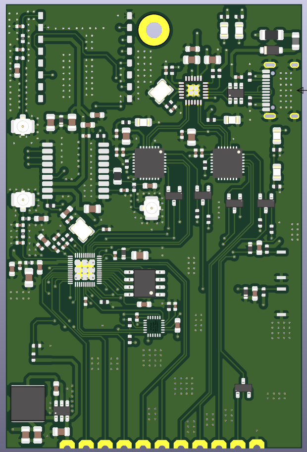
Left: Board 1, the 8-mic array (2-layer, Ø100 mm). Right: Board 2, the main board (4-layer, 50 × 75 mm).
 sound ──▶ 8 MEMS mics ──▶ K210 ──────────────────────────▶ ESP32 ──▶ LoRa ──▶ rescue dashboard
                           │ 1. capture all channels,          │ adds GPS position,
                           │    sampled on the same clock      │ IMU data, timestamp
                           │ 2. "is this a human voice?"       │
                           │ 3. "which direction?"             │
                           └─ sends only the result ───────────┘
(angle, confidence, voice yes/no)The K210 stays powered and listening all the time. It is not duty-cycled.
The system is split across two boards that solder together along an 11-pin castellated edge.
| Board | Layers | Size | Carries |
|---|---|---|---|
| Board 1: Mic array | 2 | Ø100 mm | 8× INMP441, Kendryte K210 (Sipeed M1), 12 V→5 V and 12 V→3V3 regulators |
| Board 2: Main | 4 | 50 × 75 mm | ESP32 (QFN-48), SX1262 LoRa, MAX-M10S GNSS, MPU-9250 IMU, USB-C hub + 2× USB-UART, 12 V→3V3 regulator |
| Processor | Role |
|---|---|
| Kendryte K210 (Sipeed M1) | Everything acoustic: I2S master for the array, voice detection, direction finding |
| ESP32 (QFN-48, 5 × 5 mm) | System host: LoRa, GNSS, IMU, USB, alert formatting |
Why the K210? A single K210 I2S peripheral has four data inputs driven by one clock generator. With two microphones per data line, that is eight channels sampled on exactly the same clock edges. Direction finding depends entirely on that, and the K210 provides it with nothing to synchronise. It also has a hardware FFT unit and an audio processor (APU) that can do beamforming, which we plan to evaluate later.
                 ┌──────────────────────────────────────────┐
                 │  BOARD 1: Mic array  (2-layer, Ø100 mm)  │
   8× INMP441 ───┤                                          │
   circle,       │  I2S: 4 data lines, 1 shared clock       │
   r = 45 mm     │            ↓                             │
                 │  K210 / Sipeed M1  (always on)           │
                 │   · voice detection (3-feature model)    │
                 │   · direction of arrival (GCC-PHAT)      │
                 └───────────────┬──────────────────────────┘
                                 │  11-pin castellated edge
                                 │  12 V · mic clock · 2× UART · boot/reset
                 ┌───────────────┴──────────────────────────┐
                 │  BOARD 2: Main  (4-layer, 50 × 75 mm)    │
                 │  ESP32 ── SX1262 LoRa      → U.FL        │
                 │        ── MAX-M10S GNSS    → U.FL        │
                 │        ── MPU-9250 IMU                   │
                 │        ── Wi-Fi/BLE        → U.FL        │
                 │  USB-C → CH334F hub → 2× CP2102N         │
                 └──────────────────────────────────────────┘
The IMU is there on purpose. Tapping on rubble produces both a sound and a vibration. Requiring both reduces false alarms in a way an acoustic-only system cannot.
The two halves of the design have opposite needs:
| Mic array | Main electronics | |
|---|---|---|
| What sets the size | Physics: the mics must be far apart to measure direction | Density: as small as routing allows |
| Area | Ø100 mm (≈ 7,850 mm²) | 50 × 75 mm (3,750 mm²) |
| Signals | Slow I2S lines, no RF | 3 RF paths, USB, fine-pitch parts |
| Layers needed | 2 | 4 |
On a single board, the whole area would have to be 4-layer, because the LoRa, GNSS and Wi-Fi antenna feeds need a solid ground plane and 50 Ω traces. We would be paying 4-layer prices for a large area whose only job is holding microphones 45 mm from the centre.
Both boards were ordered from Robu.in. Prices include shipping.
| Board | Layers | Area | Price paid | Price per mm² |
|---|---|---|---|---|
| Board 1: Mic array | 2 | ≈ 7,850 mm² | ₹900 | ≈ ₹0.115 |
| Board 2: Main | 4 | 3,750 mm² | ₹1,800 | ≈ ₹0.48 |
| Total (split design) | ₹2,700 |
On our order, 4-layer cost ≈ 4.2× more per mm² than 2-layer.
What a single 4-layer board would have cost, at the same ₹0.48/mm²:
| Single-board option | Area | Estimated price | Saving from splitting |
|---|---|---|---|
| Ø100 mm round (smallest that holds the array) | ≈ 7,850 mm² | ≈ ₹3,770 | ≈ 28% |
| 100 × 100 mm (more realistic once both boards' parts fit) | 10,000 mm² | ≈ ₹4,800 | ≈ 44% |
The split saves roughly 28–44% on bare PCBs. This is an estimate: fabs have minimum charges and quantity tiers, so price is not exactly proportional to area. It is still a fair comparison because both quotes came from the same supplier.
Benefits that do not show up on the invoice:
The trade-off: the castellated joint is a new failure point and cannot be probed once soldered. That is why only slow signals cross it: no RF, no high-speed bus.
Board1_2layers/Mic+MPU/)| Function | Device | Ref |
|---|---|---|
| Acoustic processor | Sipeed M1 (Kendryte K210) | U12 |
| Microphones | 8× INMP441 I2S MEMS | U1–U6, U15, U16 |
| Buck 12 V → 5 V (K210) | AP63205WU | U14 |
| Buck 12 V → 3V3 (mics) | AP63203WU | U10 |
| Power input | JST-XH 2-pin, polarised | J1 |
| Board interface | 11-pin castellated, 3.2 mm pitch | J3 |
| Buttons | Boot, Reset | SW4, SW3 |
The
Mic+MPUfolder name is historical. The MPU-9250 is on Board 2.
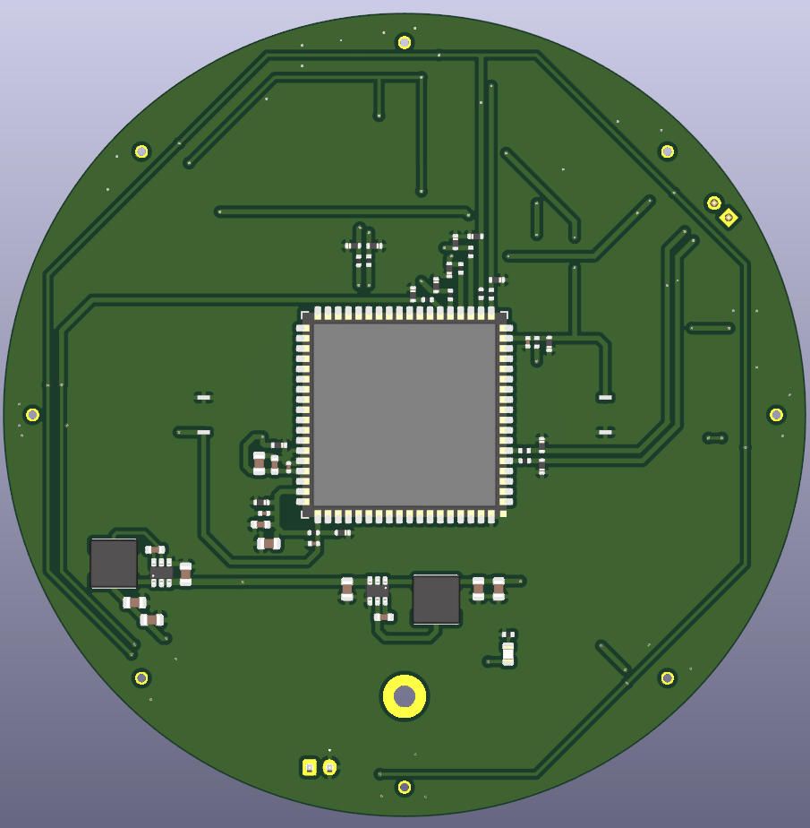
Board 1, top and bottom. The microphone sound holes are on the bottom face.
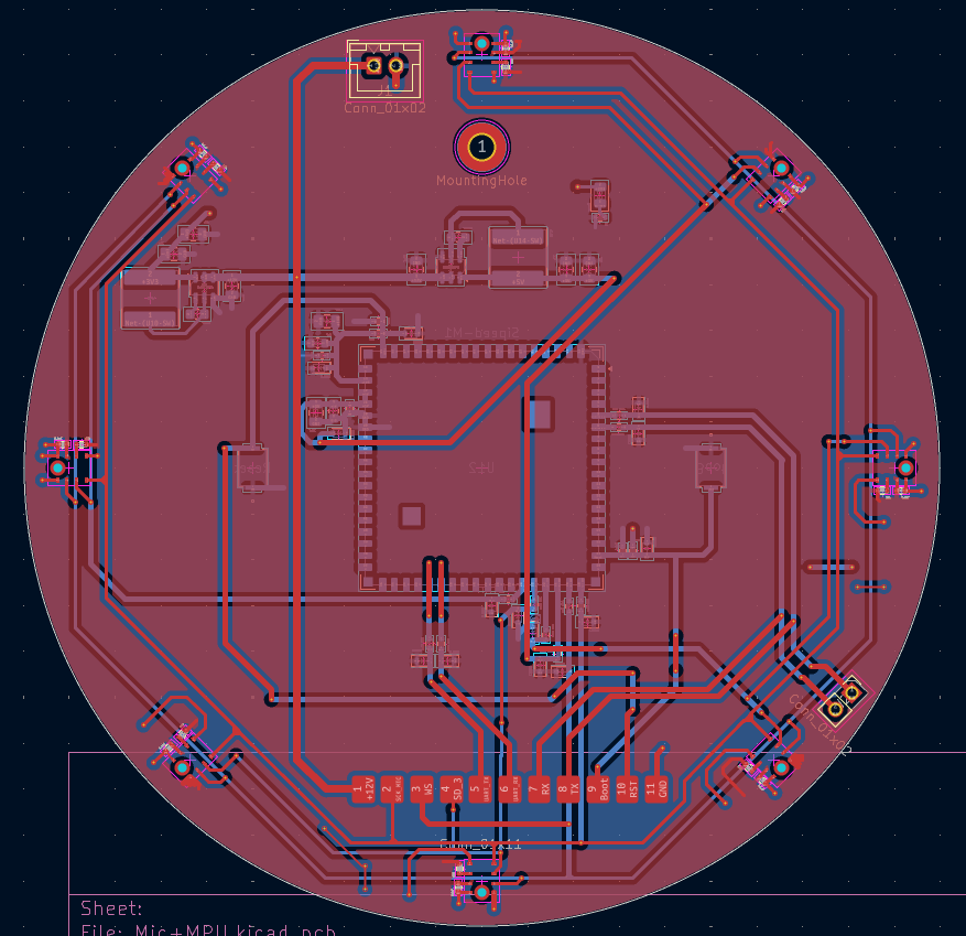
Board 1 layout in KiCad.
board2_4layers/)| Function | Device | Ref |
|---|---|---|
| Host MCU | ESP32 (QFN-48, 5 × 5 mm) | U7 |
| External SPI flash | SPI NOR, SOIC-8 | U6 |
| LoRa transceiver | SX1262 module | U1 |
| GNSS receiver | u-blox MAX-M10S | U3 |
| IMU | MPU-9250 (9-axis) | U4 |
| USB hub | CH334F | CH334F1 |
| USB-UART bridges (ESP32 + K210) | 2× CP2102N | U8, U9 |
| USB ESD protection | USBLC6-4SC6 | U2 |
| Buck 12 V → 3V3 | AP63203WU | U5 |
| Antennas | 3× U.FL: LoRa, GNSS, Wi-Fi | J2, J4, J5 |
| USB connector | USB Type-C | J1 |
| Crystals | 40 MHz (ESP32), 12 MHz (hub) | Y2, Y1 |
| Buttons | EN, BOOT | SW1, SW2 |
Stack-up: GND on F.Cu, In1.Cu and B.Cu; +3V3 on In2.Cu.
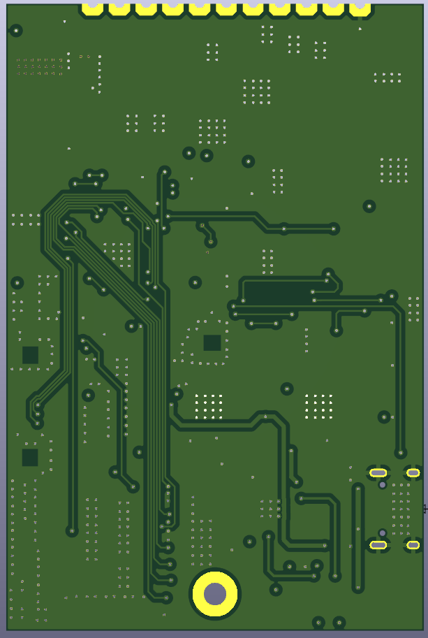
Board 2, top and bottom.
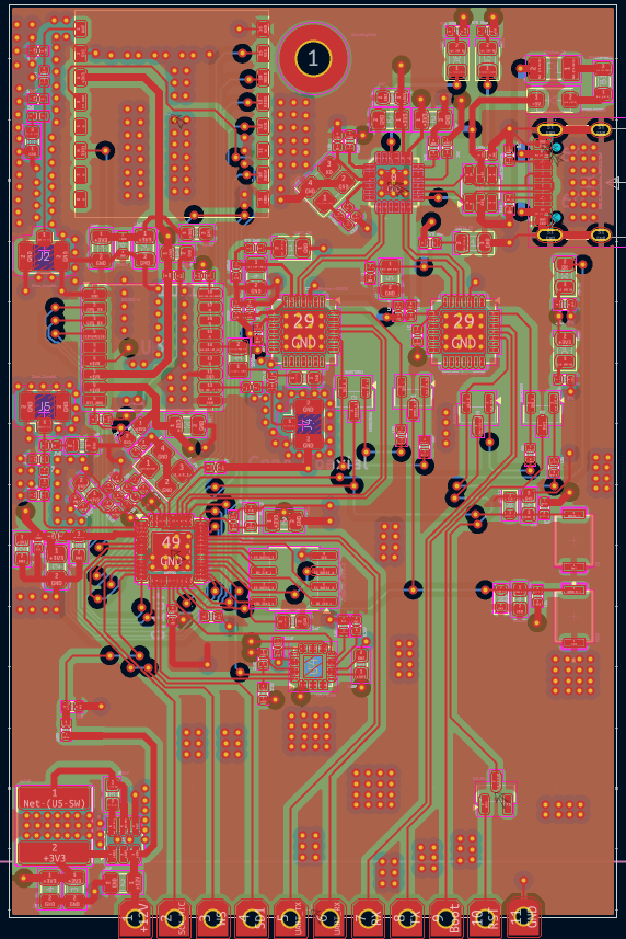
Board 2 layout in KiCad.
Eight INMP441 digital microphones on a circle of radius 45.00 mm, spaced 45° apart. Each one is rotated to face the centre, so every microphone has the same trace shape back to the K210.
Two microphones share each data line. The INMP441's L/R pin decides which
half of the stereo frame each one uses: one takes the left slot, the other the
right.
| Data line | K210 pin | Mics | Angles |
|---|---|---|---|
SD_1 | IO20 | U1, U2 | 90°, 45° |
SD_2 | IO21 | U5, U6 | 0°, 315° |
SD_3 | IO22 | U15, U16 | 270°, 225° |
SD_4 | IO23 | U3, U4 | 180°, 135° |
SCK_MIC | IO18 | shared bit clock | |
WS | IO19 | shared word select |
All eight sample on the same bit clock, so every channel is phase-coherent. This is exactly what direction finding needs, and it is why digital MEMS mics were chosen over analog mics behind a multiplexed ADC.
Every K210 IO used has a 200 Ω series resistor and an ESD diode, as Sipeed requires for the M1 module.
Sound enters from the bottom. Each mic sits over a 1.05 mm hole through the PCB, so the openings in the enclosure must be on the bottom face.
Geometry numbers:
| Quantity | Value | Why it matters |
|---|---|---|
| Adjacent mic spacing | 2r·sin(22.5°) = 34.4 mm | Spatial aliasing above c / (2 × 0.0344) ≈ 5.0 kHz |
| Opposite mic spacing | 90 mm | Longest baseline, best angle resolution |
| Max arrival-time difference | 90 mm / 343 m/s ≈ 262 µs | Only ≈ 4.2 samples at 16 kHz, so sub-sample timing is required |
About IO20. On the Sipeed Maix development board, IO20 is wired to the board's own onboard microphone, so it cannot be used for an external mic there. On our PCB the bare M1 module is used, which has no onboard microphone, so IO20 is free. This only matters if you test the firmware on a Maix board.
11 positions, 3.2 mm pitch, castellated. Board 2 solders directly onto Board 1, with no connector and no cable.
| Pin | Net | Direction | Purpose |
|---|---|---|---|
| 1 | +12V | → Board 2 | Unregulated; each board regulates locally |
| 2 | SCK_MIC | K210 → ESP32 | Mic bit clock |
| 3 | WS | K210 → ESP32 | Mic word select |
| 4 | SD1 | mics → ESP32 | Lets the ESP32 hear one mic pair (spare / diagnostics) |
| 5 | UART_TX | ESP32 → K210 | Commands |
| 6 | UART_RX | K210 → ESP32 | Results: voice flag, confidence, bearing |
| 7 | RX | K210 → CP2102N | K210 programming, transmit |
| 8 | TX | CP2102N → K210 | K210 programming, receive |
| 9 | Boot | CP2102N → K210 | IO16 boot-mode select |
| 10 | RST | CP2102N → K210 | Reset (1.8 V domain) |
| 11 | GND | Return |
TX and RX on pins 7–8 are named from the USB bridge's point of view on
both boards.
Pins 2–4 were originally intended for a low-power wake detector on the ESP32. Since the K210 now stays on all the time, that wake path is not needed. The pins stay as a spare way for the ESP32 to listen to one mic pair. If used, the ESP32 must be an I2S slave, because the K210 drives the clock.
No raw audio crosses the joint in normal operation. The mics feed the K210 directly; the UART carries only results.
12 V in (JST-XH, polarised)
   │
   ├── Board 1 ── AP63205 ──▶ +5V   → Sipeed M1 (K210)
   │           └─ AP63203 ──▶ +3V3  → 8× INMP441
   │
   └── via J3 pin 1 ──▶ Board 2 ── AP63203 ──▶ +3V3
                                     → ESP32, SX1262, MAX-M10S, MPU-9250, flash
Only 12 V and GND cross the joint, so no regulated rail loses voltage across it and the RF and audio sections do not share regulator noise.
Estimated ≈ 3.3 W total (≈ 320 mA at 12 V), mostly the K210 (≈ 1.5 W). This is an estimate and will be measured once the boards are assembled.
The firmware is plain C on the kendryte-standalone-sdk, in two CMake projects:
| Project | Build flag | Output | Use |
|---|---|---|---|
| Recorder | -DPROJ=Recorder | Recorder.bin | Streams raw mic audio to the PC for datasets and calibration |
| Detector | -DPROJ=Detector | Detector.bin | Runs voice detection and direction finding on the chip |
SAMPLE_SHIFT = 13, the smallest shift where no channel clips).For each pair of opposite microphones:
max lag = spacing / c × fs × 1.4 (40% extra for echoes and measurement error).lag_x and lag_y, and the bearing is
atan2(lag_y, lag_x).-45 dB level gate), the
correlation is too weak (< 0.08), or the delay is impossibly large.Direction finding runs on any loud enough sound, not only on speech. The voice flag is reported alongside it.
Calibration matters. On the prototype, two I2S channels start on different
word-select edges, which adds a constant offset between them. We measured
lag_x bias = −0.93 and lag_y bias = +0.95 samples, and the firmware
subtracts them (DOA_LAG_X_BIAS, DOA_LAG_Y_BIAS).
20 bytes, sent at REPORT_HZ = 20:
[5A A6] [len=0x10] [seq] [angle×10 : i16] [conf×1000 : u16] [score×100 : i16]
[level_db×10 : i16] [speech : u8] [warm : u8] [lag_x×100 : i16] [lag_y×100 : i16] [xor] [pad]
Raw-audio frames from the Recorder use:
[5A A5] [seq : u8] [blk : u16] [nch : u8] [int16 samples × blk·nch] [sum16]The sequence number lets the PC detect and count dropped bytes. Before framing, one lost byte silently turned the rest of a recording into noise while the WAV file still looked valid.
A logistic regression on 3 hand-picked features, small enough to run on the K210 as a single dot product.
| Feature | What it measures |
|---|---|
harmonicity | Strength of the pitch peak in the autocorrelation (human pitch range, lags 40–266 samples) |
voice_band_ratio | Share of energy in 300–3400 Hz (512-point Hann-window FFTs) |
snr_db | Level above a rolling noise floor (20th percentile over the last 8 s) |
Accoustic_Sensing_Node/ML/). The feature scaler is folded into the weights and
exported as vad3_model.h, so the chip does no extra scaling.VAD_SMOOTH_K = 3).FEATURE_VERSION = 4. The firmware and Python feature code must match. The
version number makes a mismatch obvious.Our own recordings (INMP_441_Dataset/) are combined with public datasets
(Public_Dataset/). Every file goes through a quality check (dropped bytes,
clipping, DC offset, rumble, SNR) before it is used.
We also run a confound check: a classifier trained only on the background of each recording, with the speech removed. If it can still tell the classes apart, the model could be learning which session a clip came from instead of whether someone is speaking.
| Dataset version | Background-only AUC | Target |
|---|---|---|
| First dataset | 0.905 – 0.94 | < 0.65 |
| Latest | 0.812 | < 0.65 |
It is improving, but still above target. Recording speech and non-speech interleaved in the same session, room and distance is the fix in progress.
Python tools on the PC, all reachable from one entry point:
python capstone.py --help| Command | What it does |
|---|---|
status, devices, linktest, inspect | Check setup, list serial ports, test the link, inspect captures |
record | Record labelled clips from the board |
qc, filters | Dataset quality check, filter tests |
train, train-corpus, export | Train the model and export vad3_model.h |
predict | Run the model on WAV files |
serve, monitor, gui | Live API + dashboard, console monitor, desktop GUI (sar_gui.py) |
API server (api_server.py): reads the K210's result packets from serial
and serves them over HTTP on all interfaces (port 8000 by default), so a phone
on the same Wi-Fi hotspot can open the dashboard.
| Endpoint | Returns |
|---|---|
/api/detections | Detections from the last 15 s |
/api/state | Latest bearing, level, voice flag |
/api/threshold | Read or change the detection threshold |
/api/health | Server and serial-link status |
/ | dashboard.html, the radial display |
It uses a threaded server with HTTP/1.1 keep-alive, which fixed the lag we saw on phones over a hotspot.
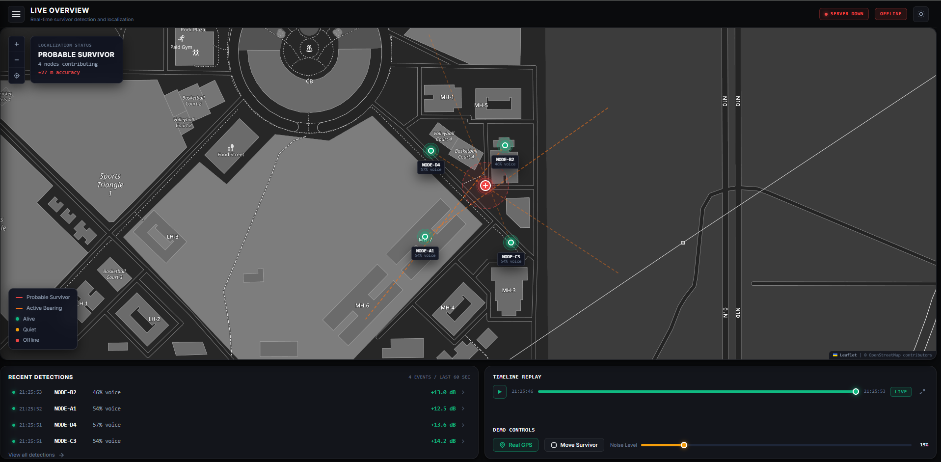
Live dashboard in the browser.
Before the PCBs, the full pipeline was built on a breadboard: a Sipeed Maix board with 4 INMP441 mics in a 40 mm square. Opposite corners are paired, so the baseline is the square's diagonal, 56.6 mm.
What works on the prototype:
A measured accuracy table (true angle vs reported angle, several distances) will be added once the PCB is assembled. Numbers from the breadboard are not representative of the final board, so they are not published here.
Recorder and Detector CMake projectsvad3_model.h, FEATURE_VERSION = 4)capstone.py single entry point, sar_gui.py desktop GUI| # | Item | Where | What to do |
|---|---|---|---|
| 1 | DOA constants are for the 4-mic breadboard | Firmware | DOA_SPACING_MM, SAMPLE_SHIFT and both lag biases must be re-measured on the circular array (opposite pair = 90 mm) |
| 2 | Every opposite pair spans two data lines | Firmware | e.g. 0° is on SD_2 and 180° on SD_4. Each data line may have its own timing offset, so calibrate a per-data-line offset at bring-up (the prototype needed ≈ ±0.9 samples) |
| 3 | Channel order is not ring order | Firmware | K210 inputs D0–D3 = SD_4, SD_3, SD_2, SD_1. Build the channel→angle table and confirm it with a tap test at each mic |
| 4 | Dataset confound | ML | Background-only AUC 0.812, target < 0.65. Record both classes interleaved in the same session |
| 5 | Measured DOA accuracy table | Testing | After PCB assembly |
| 6 | Flash part name | Board 2 | U6 value field shows AT25SF081; update it to the part actually fitted |
| 7 | CP2102N no-connect pins | Board 2 | Add no-connect flags on U8/U9 pin 10 (cosmetic, clean ERC) |
| 8 | Stale BOM export | Board 2 | Accoustic_Sensing_Node.csv is from an older revision; re-export from KiCad |
| 9 | Battery operation | Both | Node runs from 12 V only; battery + boost planned |
| 10 | One M2.5 mounting hole per board | Both | Add more before the enclosure is fixed |
| 11 | Enclosure | Mechanical | Sound openings on the bottom face, antenna clearance, survives drops |
Everything for the acoustic node lives in the Accoustic_Sensing_Node/ folder:
Accoustic_Sensing_Node/
├── README.md                     ← copy of this file
├── images/                       ← all pictures used in this README
│
├── Board1_2layers/
│   ├── Mic+MPU/                  KiCad project: mic array board (2-layer)
│   │   ├── Mic.pretty/           INMP441 footprint (with sound hole)
│   │   ├── Connectors.pretty/    11-pin castellated footprint
│   │   └── output/               Gerbers as ordered
│   └── mic/INMP441.kicad_mod
│
├── board2_4layers/               KiCad project: main board (4-layer)
│   ├── *.pretty/                 custom footprints (LoRa, GNSS, USB hub, edge pads)
│   └── Output/                   Gerbers + drill as ordered
│
├── Recording_Via_IOT_Devices/
│   ├── firmware/
│   │   ├── K210/src/Recorder/    raw multi-channel streaming
│   │   ├── K210/src/Detector/    main_detector.c, sar_features.c, sar_doa.c, vad3_model.h
│   │   └── esp32_1mic/           single-mic ESP32 recorder (dataset collection)
│   ├── record.py, devices.py     recorder and per-board serial settings
│   ├── api_server.py             HTTP API + serial reader
│   ├── dashboard.html            radial live display
│ ├── detector_monitor.py console monitorDatasets (INMP_441_Dataset/, Public_Dataset/) are not stored in the repo
because of their size.
Run everything from inside the acoustic folder:
cd Accoustic_Sensing_Nodepip install -r requirements.txt
python capstone.py statusTry the dashboard with no hardware:
python Recording_Via_IOT_Devices/api_server.py --demo
# open http://localhost:8000cd Recording_Via_IOT_Devices/firmware/K210
mkdir build && cd build
cmake .. -DPROJ=Detector -DTOOLCHAIN=/opt/kendryte-toolchain/bin
make
kflash -p COM12 -b 1500000 Detector.binDelete the
build/folder when switching betweenRecorderandDetector. CMake caches the project name, so otherwise it silently builds the old one again.
See BUILD.md for Windows details.
python Recording_Via_IOT_Devices/api_server.py --port COM12
# optional: --capture session.bin  (save the raw stream to replay later)
#           --wav heard.wav        (save what the detector is hearing)
#           --replay session.bin   (replay a saved session, no hardware)
Then open http://<pc-ip>:8000 on any device on the same network.
Things learned the hard way, kept here so they are not learned twice:
devices.py clears both before opening the port.Main use: search-and-rescue: locating people trapped under collapsed buildings. Several nodes across a site turn a large, uncertain search area into a short list of places worth digging.
Other uses: perimeter and intrusion detection, wildlife monitoring, noise source mapping, remote sensor networks with human-presence detection.
Under active development. License to be decided.
| Qty | Value | Footprint | References |
|---|---|---|---|
| 13 | 10k | Resistor_SMD:R_0402_1005Metric | R8, R9, R10, R15, R16, R17, R18, R20, R24, R25, R26, R31, R32 |
| 9 | 1uF | Capacitor_SMD:C_0603_1608Metric | C3, C19, C28, C29, C35, C36, C38, C44, C45 |
| 6 | 0.1uF | Capacitor_SMD:C_0402_1005Metric | C16, C18, C31, C40, C42, C43 |
| 6 | 100nF | Capacitor_SMD:C_0402_1005Metric | C46, C48, C49, C50, C52, C53 |
| 5 | 2nH | Inductor_SMD:L_0402_1005Metric | L1, L2, L4, L5, L6 |
| 4 | 1.5pF | Capacitor_SMD:C_0402_1005Metric | C5, C6, C30, C33 |
| 4 | 100nF | Capacitor_SMD:C_0603_1608Metric | C1, C8, C14, C37 |
| 4 | 10uF | Capacitor_SMD:C_0805_2012Metric | C9, C20, C22, C24 |
| 4 | 470 Ohm | Resistor_SMD:R_0402_1005Metric | R13, R14, R28, R30 |
| 4 | ESD3.3 | Diode_SMD:D_SOD-523 | D1, D8, D9, D10 |
| 4 | MMBT3904 | Package_TO_SOT_SMD:SOT-23 | Q1, Q2, Q3, Q4 |
| 3 | 22uF | Capacitor_SMD:C_0805_2012Metric | C2, C4, C27 |
| 3 | Conn_Coaxial | Connector_Coaxial:U.FL_Hirose_U.FL-R-SMT-1_Vertical | J2, J4, J5 |
| 2 | 0 Ohm | Resistor_SMD:R_0402_1005Metric | R12, R22 |
| 2 | 10nF | Capacitor_SMD:C_0603_1608Metric | C10, C15 |
| 2 | 12pF | Capacitor_SMD:C_0402_1005Metric | C11, C13 |
| 2 | 1K | Resistor_SMD:R_0402_1005Metric | R27, R29 |
| 2 | 1k | Resistor_SMD:R_0402_1005Metric | R1, R3 |
| 2 | 2.2K | Resistor_SMD:R_0402_1005Metric | R6, R7 |
| 2 | 22pF | Capacitor_SMD:C_0402_1005Metric | C21, C23 |
| 2 | 22u | Capacitor_SMD:C_0805_2012Metric | C39, C41 |
| 2 | 4.7uF | Capacitor_SMD:C_0805_2012Metric | C47, C51 |
| 2 | 5.1k | Resistor_SMD:R_0402_1005Metric | R4, R5 |
| 2 | CP2102N-Axx-xQFN28 | Package_DFN_QFN:QFN-28-1EP_5x5mm_P0.5mm_EP3.35x3.35mm | U8, U9 |
| 2 | UART1_ON | LED_SMD:LED_0805_2012Metric | D11, D12 |
| 1 | 100k | Resistor_SMD:R_0402_1005Metric | R19 |
| 1 | 100n | Capacitor_SMD:C_0402_1005Metric | C7 |
| 1 | 100pF | Capacitor_SMD:C_0402_1005Metric | C34 |
| 1 | 10Ohm | Resistor_SMD:R_0805_2012Metric | R11 |
| 1 | 10nF | Capacitor_SMD:C_0402_1005Metric | C26 |
| 1 | 10uF | Capacitor_SMD:C_0805_2012Metric_Pad1.18x1.45mm_HandSolder | C25 |
| 1 | 12MHz | Crystal:Crystal_SMD_3225-4Pin_3.2x2.5mm | Y1 |
| 1 | 1uF | Capacitor_SMD:C_0402_1005Metric | C12 |
| 1 | 20k | Resistor_SMD:R_0402_1005Metric | R23 |
| 1 | 27nH | Inductor_SMD:L_0402_1005Metric | L3 |
| 1 | 3.3nF | Capacitor_SMD:C_0402_1005Metric | C32 |
| 1 | 30k | Resistor_SMD:R_0402_1005Metric | R21 |
| 1 | 33pF | Capacitor_SMD:C_0402_1005Metric | C17 |
| 1 | 4.7uH | Inductor_SMD:L_Sunlord_SWPA6020S | L7 |
| 1 | 40MHz | Crystal:Crystal_SMD_3225-4Pin_3.2x2.5mm | Y2 |
| 1 | AP63203WU | Package_TO_SOT_SMD:TSOT-23-6 | U5 |
| 1 | AT25SF081-SSHD-X | Package_SO:SOIC-8_3.9x4.9mm_P1.27mm | U6 |
| 1 | BAT_54 | Package_TO_SOT_SMD:SOT-23 | D13 |
| 1 | BLM21PG220 | Inductor_SMD:L_0805_2012Metric | FB1 |
| 1 | BOOT | Button_Switch_SMD:SW_CS1213AGF260_CRS | SW2 |
| 1 | Conn_01x11 | SMD_PAD:Castellated_Edge_11P_2.54 | J3 |
| 1 | EN | Button_Switch_SMD:SW_CS1213AGF260_CRS | SW1 |
| 1 | ESP32 | Package_DFN_QFN:QFN-48-1EP_5x5mm_P0.35mm_EP3.7x3.7mm | U7 |
| 1 | ESP_32 | LED_SMD:LED_0805_2012Metric | D2 |
| 1 | MAX-M10S | RF_GPS:ublox_MAX | U3 |
| 1 | MPU-9250 | Sensor_Motion:InvenSense_QFN-24_3x3mm_P0.4mm | U4 |
| 1 | MountingHole | MountingHole:MountingHole_2.7mm_M2.5_Pad_TopBottom | H1 |
| 1 | PMEG4020EP | Diode_SMD:D_SOD-123F | D5 |
| 1 | Polyfuse 2A | Fuse:Fuse_1206_3216Metric | F1 |
| 1 | Power | LED_SMD:LED_0805_2012Metric | D4 |
| 1 | SX1262 | LORA:SX1262-B | U1 |
| 1 | USB1 | LED_SMD:LED_0805_2012Metric | D6 |
| 1 | USB2 | LED_SMD:LED_0805_2012Metric | D7 |
| 1 | USBLC6-4SC6 | Package_TO_SOT_SMD:SOT-23-6 | U2 |
| 1 | USB_C_Receptacle_USB2.0_16P | Connector_USB:USB_C_Receptacle_HCTL_HC-TYPE-C-16P-01A | J1 |
| 1 | ~ | USB_HUB:QFN24_4MM | CH334F1 |
irocobble/CA_LR_ES
Open-source ESP32-S3 edge computing module with LoRa, GPS, external flash, MicroSD, and expansion support for long-range IoT applications.

irocobble/CA_LR_ES
Open-source ESP32-S3 edge computing module with LoRa, GPS, external flash, MicroSD, and expansion support for long-range IoT applications.


irocobble/LED_Matrix
design of custom PCB that drives an 8×8 LED matrix (64 LEDs) using an STM32F103C8T6

crnicholson/StratoSoar-MK2
StratoSoar is an engineering project that aims to be able to fly a glider (dropped from a high-altitude balloon), down to any selected coordinates.

leptun/Avionus_Flight_Controller
Controller board for autonomous RC plane


felixfelix-bot/balloon-fresh
Open-source pico-balloon hardware and firmware, multi-radio LoRa/FLRC mesh networking, ground stations, and RF range-test tooling.

Yorha-7/Rocket
in this repo we are simulating rocket basic physics and make a onboard flight computer which utilizes MCU, gyro, pressure sensor, fin servo controls, to get realtime target tracking abilities to a solid fuel rocket.

It measures 50 × 75 mm and has 4 copper layers, 1.57 mm thick.
129 parts, built around the AP63203WU, MAX-M10S, MPU-9250 and USBLC6-4SC6. The full list of its parts is on this page, with links to each part's symbol and footprint where PCBKit's library has them.
From the irocobble/CA_LR_ES repository on GitHub, at the commit this page was made from: the board is Accoustic_Sensing_Node/board2_4layers/Accoustic_Sensing_Node.kicad_pcb and its schematic Accoustic_Sensing_Node/Accoustic_Sensing_Node.kicad_sch. PCBKit opens the board in the browser, with nothing to install.
Its repository states no licence, so its author keeps all rights: ask irocobble before reusing the design.